
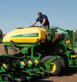
db120 48row30 planter
Planter
- 120-ft. toolbar with 48 rows on 30-in. spacing
- Available in mini-hopper MaxEmerge™ 5 row unit
- Requires a minimum 370-hp tractor with Category 5 drawbar and five hydraulic SCVs plus power beyond
View Product Brochure
Features
SeedStar XP overview
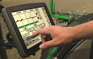 SeedStar XP shown on the GreenStar™ 3 2630 Display
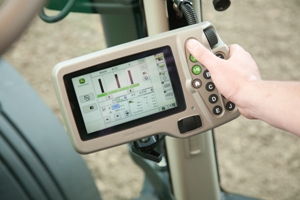 SeedStar XP shown on the GreenStar 2 1800 Display
Building upon the foundation of SeedStar 2, the SeedStar XP system takes planter monitoring to the next level. SeedStar XP is compatible with the GreenStar 2 1800 and 2600 Displays, GreenStar 3 2630 Display, the Gen 4 4200 CommandCenter™ Display, the Gen 4 4600 CommandCenter Display, the 4240 Universal Display, and the 4640 Universal Display. SeedStar XP is not compatible with the Gen 4 Extended Monitor.
Specific information about how the planter is performing enables the operator to make needed adjustments for implement optimization.
The SeedStar XP planting functions are fully integrated with the full spectrum of Precision Ag Technology applications such as Swath Control Pro™ system for planters, GreenStar AutoTrac™ assisted steering system, John Deere Operations Center, Documentation, and others. Integrated planting technologies for better asset utilization and ease of use is just part of what SeedStar XP provides.
SeedStar XP seed singulation monitoring
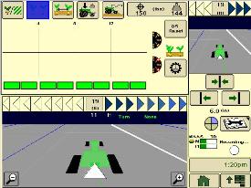
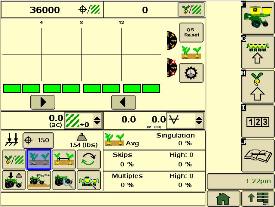 SeedStar XP seed singulation planter run page
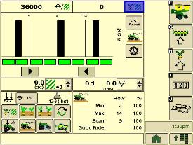
Understanding the meter singulation performance on the planter is critical to minimizing the amount of seed multiples and skips. As a result, the SeedStar XP monitoring system provides real-time information from the row-units about the overall seed singulation performance.
As seen in the screen shot image above, seed multiple information is displayed on the top portion of the planter-at-a-glance bar with seed skip information on the lower portion. This provides the operator a better understanding of relative seed multiple and skip data on a row-unit basis, all within one easy glance.
Also, within the seed singulation planter run page, information about row-units with the highest percentage of seed multiples and skips is provided in order to make necessary adjustments for better planter optimization.
SeedStar XP row-unit ride dynamics planter run page
 SeedStar XP ride dynamics planter run page
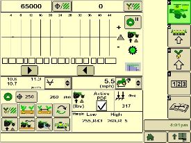
While operating a planter, travel speed and field conditions can affect the amount of row-unit bounce that is experienced. Excessive row-unit bounce or vertical motion can cause problems with meter performance. To better understand the amount of row-unit vertical motion when travelling through a field, the SeedStar XP monitoring system provides real-time information on row-unit ride dynamics.
As seen in the ride dynamics planter-at-a-glance screen shot image above, the SeedStar XP system provides ride dynamic information for each sensor node that is mounted on the planter. Each sensor node transmits ride dynamic information for each planter frame section to allow for the operator to make necessary operating adjustments to improve overall planting performance.
SeedStar XP row-unit downforce planter run page
 SeedStar XP downforce planter run page
As row-unit downforce systems gradually change from heavy-duty downforce springs to pneumatic downforce, being able to understand the amount of as-applied row-unit downforce is needed while operating the planter.
With various soil conditions, moisture, etc. experienced while planting, it is imperative to have the ability to change actual row-unit downforce to have enough force for the Tru-Vee openers to penetrate the soil media. However, in some conditions, having too much downforce applied to the row-units for effective opener penetration could cause problems with side wall compaction from the gauge wheel.
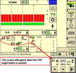
Side wall compaction within the seed furrow can cause hatchet roots to develop, or roots that do not have the ability to penetrate the seed furrow soil media. This could lead to poor plant emergence and eventually lower overall yield performance.
With the SeedStar XP monitoring system, row-unit downforce information is measured by the downforce sensor and sensor nodes and transmitted to the GreenStar 2 Display in the tractor cab (as seen in the image above). The row-unit downforce information is displayed on the top portion of the planter-at-a-glance bar with more row-unit downforce information on the lower portion.
Two different control options are available on 1775NT, 1795, and DB Series Planters for pneumatic downforce. The base pneumatic downforce system requires manual control of the downforce to maintain the desired planting results or row-unit margin. Optional active pneumatic downforce takes SeedStar XP even further by removing constant downforce adjustments from the operator and actively controlling the downforce system to maintain a desired target margin.
SeedStar XP seed spacing monitoring
 SeedStar XP seed spacing planter run page
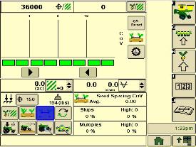
Throughout the planting process, obtaining good seed spacing is critical toward achieving plant growing conditions for maximum yield potential.
Today, many items are adjusted on the planter prior to planting to optimize overall seed spacing performance. After such adjustments are made, information about the actual seed spacing performance during planting was missing within the planter monitoring system. Now with SeedStar XP, seed spacing information is transmitted live via the GreenStar display to show the operator exactly what is happening with the planter behind them.
The SeedStar XP transmits seed spacing information onto the planter-at-a-glance bar for easy understanding of planter seed spacing performance. Also, information about seed skips and multiples is provided to help understand actual planter meter performance and other related system functions in order to make necessary adjustments if needed.
NOTE: Seed spacing and seed singulation information is only available when planting crops with seed drop rates below 40 seeds per second such as corn. With higher population crops such as soybeans the system does not provide spacing and singulation information because the number of seeds dropping per second is much higher.
SeedStar XP full planter performance page
 SeedStar XP planter details
 With the capability of monitoring differences in planting performance items such as seed singulation and row-unit downforce, having one screen to view all planter performance elements is needed to understand the whole planting system. SeedStar XP combines all of the various planting performance elements into one full-color, planter overview screen to enable for a quick understanding of relative planting functionality.
SeedStar XP half screens and other features
 SeedStar XP seed singulation half screen
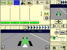 SeedStar XP seed spacing half screen
Other SeedStar XP monitoring features include:
- Capable of monitoring individual row-unit and overall planter performance in terms of seed spacing, singulation, and row-unit downforce
- Split-screen applications to enable use of popular guidance features such as AutoTrac assisted steering system
- On-screen indication of sensor node/downforce sensor assemblies once configured within the monitor settings application
- Full-color display icons for easy recognition and overall aesthetics
- Pneumatic downforce system controls with the GS display application
SeedStar 2 monitoring original features
SeedStar XP retains all of those SeedStar 2 features that producers value and have come to expect:
- Planter-at-a-glance – allows operator to view relative population levels of all rows on one screen.
- Automatic valve calibration – with the SeedStar variable-rate drive (VRD), this is now completed automatically. There is no longer a need to manually calibrate the hydraulic valves.
- Increased population updates – SeedStar will now update population levels once per second at planter start up then approximately once every three seconds.
- Mapping of actual seed rates – when combined with documentation, actual and target seeding rates can now be mapped in John Deere Operations Center.
- Reprogrammable utilizing controller area network (CAN) via Service ADVISOR™ diagnostics system.
- Improved diagnostics/event recorder – on SeedStar VRD planters, additional diagnostic information is available, as well as an event recorder to capture system performance data at a specific point in time.
- Ability to run motors at different population levels – on SeedStar VRD, operators running multiple motor systems can run each motor at a different speed, allowing different population levels within a planter.
- User-configurable high fertilizer pressure alarm – allows the operator to be warned when fertilizer pressure reaches a specific level.
- Automatic quick-start for SeedStar VRD – no longer does the operator need to press the quick-start button on end row turns to resume planting.
- Automatic tractor speed source selection – when equipped with an 8000/9000 Series Tractor, the system selects the radar speed or allows for manual speed input selection.
Components and operation
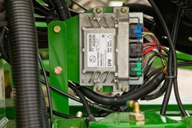
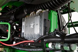 Planter main 2 controller
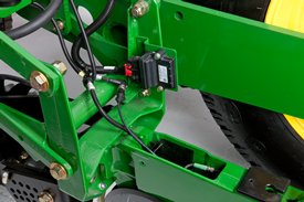 Sensor node assembly installed
The SeedStar XP monitoring system contains the following components in order to support the planting data transfer to the GreenStar 2 Displays:
- Seed monitor/variable-rate (SMVR) controller with model year 2011 or newer software
- Planter main 2 controller (installed on all SeedStar XP eligible models for model year 2011 or newer)
- Sensor node(s)
- Downforce sensor assembly
The planter main 2 controller processes the row-unit data from the sensor node assemblies located on the row-unit head casting. The processed information is then sent to the SMVR controller to be integrated into the displayed information being sent to the GreenStar Display.
Downforce sensor assemblies are found on row-units with sensor nodes installed. The downforce sensor assembly is assembled with the gauge wheel depth-adjustment handle and provides gauge wheel pressure information to the respective sensor node for data processing.
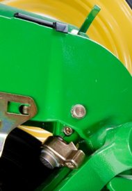 Downforce sensor installed
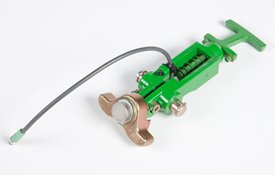 Downforce sensor assembly
Depending on the planter size, different configurations of sensor nodes and downforce sensors are installed in support of the SeedStar XP monitoring system.
Option code 2625 – Liquid fertilizer with row-unit mounted in-furrow applicator:
- This option contains a ground driven pump, plumbing to a manifold, and routing to each row-unit. The in-furrow applicator places fertilizer after the seed and before the closing wheels.
The DB60 24Row Split 47 Planter and DB60 24Row Split 48 Planter applies fertilizer on 76.2-cm (30-in.) row spacing only.
 Drawbar hitch
A factory-installed, optional drawbar hitch is available for use with 1775NT 16- and 24-Row, 1775NT Central Commodity System (CCS™) 16- and 24-Row, and 12.2-m (40-ft) 1795 Planters. For all DB models the drawbar hitch is in base. All DB models are available with Category 5 drawbar hitch. The following DB models are not available with Category 4 drawbar hitch: DB80 48R20, DB88 48R22, DB90 36R30, DB90 54R20, and DB120 48R30.
The planter drawbar hitch provides easy operation with plenty of ground clearance. The hitch design utilizes a hydraulic cylinder to raise the planter hitch for transport. Hydraulic oil for the hitch cylinder on 1775NT and 1795 Planters comes from the row marker system. Activation of this cylinder is accomplished using a single switch on the display and the marker selective control valve (SCV).
Due to the hydraulic system design, the drawbar hitch requires the planter be equipped with independent markers (not tied to planter lift circuit). Removal of markers from all planters, except the 1775NT 24Row30, makes the drawbar hitch inoperable. The 1775NT 24Row30 is the only planter where the drawbar hitch, less markers, is a valid combination.
For planting on 38.1-cm (15-in.) row spacing with a 16/32-Row 1795 Planter, the drawbar needs to be offset 19-cm (7.5-in.) on the tractor to center the planting rows behind the tractor. When the 16/32 1795 has a drawbar hitch, operators may not be able to offset the hitch to the exact specifications of 19-cm (7.5-in.) when planting in 38.1-cm (15-in.) operation, and could be off as much as a 1.3-cm (0.5-in.). To compensate, additional adjustments to the marker will be necessary.
When using a guidance system such as parallel tracking or AutoTrac™ assisted steering system, operators will need to use their implement offset when planting with all rows on 1795 Planters equipped with the drawbar hitch to compensate for the offset.
The drawbar hitch is ideal for those who have 9000 Series Tractors without a 3-point hitch. For these, the planter drawbar hitch is the economical choice instead of adding a 3-point hitch.
To accept the planter drawbar hitch, the tractor drawbar must be ordered with, or upgraded to, a Category 4 drawbar with the heavy-duty package or Category 5 to be compatible. Track tractors with wide-swinging drawbars are not compatible with the planter drawbar hitch due to a lower hitch-load capacity.
Each 1795 or 1775NT Planter ordered with the drawbar hitch will be shipped with a Category 4 hitch link installed. A Category 5 hitch link is also shipped with the planter if the planter is to be used with a Category 5 drawbar. See pre-delivery instructions included with the planter for changeover information.
Compatibility:
- Category 5 implement hitch links are not compatible with Category 4 tractor drawbars.
- Category 5 tractor drawbars are not compatible with Category 4 implement hitch links.
This hitch also adds 0.6-m (2-ft) to planter length during transport and field operation. There are some combinations of planter options that are not compatible with the drawbar hitch option due to tractor drawbar limitations.
Heavy-duty adjustable downforce springs
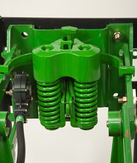 Heavy-duty adjustable downforce spring
Planter row-unit downforce is an important factor to ensure consistent and proper depth control. The heavy-duty adjustable downforce feature provides up to 181.4 kg (400 lb) of downforce. There are four settings available to allow the operator to choose the amount of downforce required for the condition: 0 kg (0 lb), 56.7 kg (125 lb), 113.4 kg (250 lb), and 181.4 kg (400 lb).
Compatibility: 1705, 1715, 1725, 1735, 1755, 1765, 1765NT, 1775 Flex, and 1785
Standard pneumatic downforce system
Pneumatic downforce provides convenient, simple adjustment of downforce for the whole planter from one location. The amount of downforce applied is infinitely adjustable from 0 to 181.4 kg (0 to 400 lb). Pneumatic downforce provides more consistent downforce throughout the range of row-unit travel than mechanical spring downforce systems.
Features include:
- 9.5-mm (3/8-in.) air delivery line instead of the 6.4-mm (1/4-in.) line used on model year 2010 and older planters.
- Air compressor assembly increased duty cycle. With this compressor, it provides a 47 percent increase in maximum air flow delivery compared to the prior air compressor.
- Pneumatic air bags with 9.5-mm (3/8-in.) air line inlets that have greater durability.
 Pneumatic downforce spring
Each row-unit has a single rubber air bag located between the parallel arms. The air bags are hooked in parallel so that air can be added or released from all rows at once from one location.
The individual pneumatic downforce air bag assemblies, air compressor units, and 9.5-mm (3/8-in.) delivery lines are also available as an attachment for field conversion.
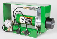 Pneumatic downforce compressor and gauge
An improved compressor is used to charge the pneumatic system. This compressor can be located on the planter frame or in the tractor cab if desired. A gauge at the compressor indicates the amount of downforce being applied.
From the factory, integral planter models with pneumatic downforce will have an improved air compressor assembly with an in-cab mounting bracket, except for the 1725 16-row and 1725 Central Commodity System (CCS™) twin-row planters, which will have the air compressor assembly mounted on the planter frame. For drawn planter models, the 1755, 1765, 1765NT, 1775 Front-Fold, and 1785 Drawn Planters will have the air compressor assembly installed either on the outer hitch or wing frame members when the pneumatic downforce system is installed.
Base equipment on: 1705, 1715, 1725, 1735, 1755, 1765, 1765NT, 1775 and 1785.
Integrated pneumatic downforce system
The functional features of the integrated system are the same as the standard pneumatic system, explained above, with the addition of control through the GreenStar™ display.
System control with the GreenStar display
 Pneumatic downforce control in GreenStar 2 Display
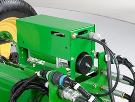 Air compressor mounted on 1775NT outer hitch
On 1725 16-row, 1725 CCS TR, 1775NT, 1775NT CCS, 1795, DR, and DB Series Planter models, the air compressor will be mounted on the outer hitch or frame assembly. Since the air compressor assembly is mounted on the outer hitch (as noted in the picture above) or frame, adjustments for row-unit downforce and related system pressures will be made electronically with the GreenStar display.
When adjusting the amount of row-unit downforce using the GreenStar display, the operator will select the amount of downforce (kg [lb]) to be applied across the planter. Depending on the soil conditions at hand, the operator might need to adjust the relative amount of row-unit downforce being applied during the planting operation. The integrated pneumatic downforce controls within the GreenStar display will only allow for set-point operation and not automatic control as the planter is operating in different soil conditions. The pneumatic downforce system does not have the capability to automatically adjust downforce.
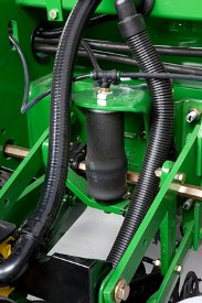
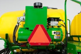
On-board air storage
 Onboard air storage installed on 1775NT 24R30
The 1725 16-row, 1725 CCS TR, 1775NT, 1775NT CCS, 1795, DR, and DB Series planters will have onboard air storage to increase the overall response time when making a row-unit downforce adjustment from the GreenStar display. The onboard air storage is comprised of a 18.9-L (5-gal.) storage tank with valve assembly.
Base equipment on: 1725 CCS, 1725 16-row, 1725T, 1775NT, 1775NT CCS, 1795, DR, and DB Series Planters with MaxEmerge™ 5 row-units. MaxEmerge 5e and ExactEmerge™ equipped planters come with active pneumatic downforce in base.
Active pneumatic downforce
 Active downforce compressor assembly
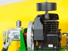 Hydraulic motor
A hydraulically driven compressor works with the SeedStar™ 3 HP system and SeedStar XP system to automate downforce control. Just set the row-unit target margin value and the active pneumatic downforce system works automatically. The system will make sure the planter maintains this value, achieving precise soil penetration, and consistent planting depth, without sidewall soil compaction. From the factory, the system is set at 45.4 kg (100 lb) target downforce margin, but may be modified for varying field conditions. This frees the operator from constantly making manual downforce adjustments as conditions change.
This system offers a split-rank control feature for 1795 and DB Split-Row Planters. On split-row planters, active downforce will control the front and rear rows independently. This compensates for differing downforce requirements between the ranks that can be caused by things like different tillage or insecticide attachments and will help maintain an accurate planting depth and consistent margin across all the rows.
Active pneumatic downforce is available as factory installed or as an attachment for field conversion.
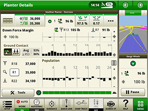
SeedStar XP row-unit downforce planter run page
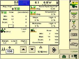
SeedStar XP downforce planter run pageActive downforce control is integrated into SeedStar XP and SeedStar 3 HP monitoring systems.
Margin is the amount of weight riding on the depth gauge wheels that ensures desired firming of the seedbed as set by the operator.
Once a target margin has been defined, enter the value into SeedStar XP or SeedStar 3 HP and let active downforce do the rest. The system will actively adjust the air pressure in the air bags to maintain a constant margin across the planter. The changes in air pressure will change the amount of downforce placed on the row-unit, compensating and reacting for varying conditions through the field whether it is different tillage practices, soil types, or moisture.
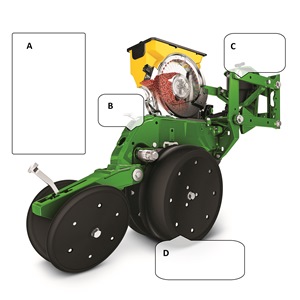 Downforce and margin example
- A - Margin – amount of additional downforce applied to a row-unit above and beyond what is required for penetration to achieve planting depth. This additional weight will ride on the depth gauge wheels. 54.4 kg (120 lb) + 36.3 kg (80 lb) = 90.7 kg (200 lb) – 68 kg (150 lb) = 22.7 kg (50 lb) of margin
- B - Weight of row-unit - 54.4 kg (120 lb)
- C - Downforce – force that is applied to the row-unit by the air bag circuit - 36.3 kg (80 lb)
- D - Resistance from soil - 68 kg (150 lb)
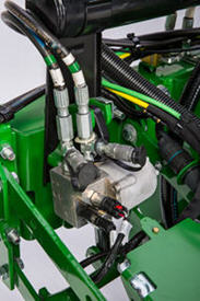
Hydraulically driven compressor
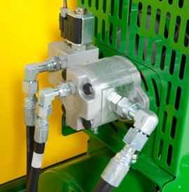 Hydraulic motor
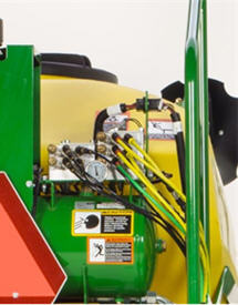 Pneumatic valve
The hydraulically driven air compressor can deliver up to eight times the air flow, allowing for more and faster downforce changes to be made. This more robust design features a 37.8-L (10-gal.) storage tank across all models with active downforce.
At approximately 15.1 L/min (4 gpm), hydraulic demands are low and ties into the machine’s lift and CCS hydraulic circuit so it does not require any additional selective control valves (SCVs). The SeedStar XP and SeedStar 3 HP monitoring systems work with the compressor and valve assembly to regulate air to downforce springs, enabling the active control.
Another feature of John Deere active downforce is the ability for the pneumatic valve to independently control split-rank machines. This system senses the downforce needs from the front and rear ranks separately and independently adjusts air pressures with the dual-rank pneumatic valve when equipped. Active pneumatic downforce requires SeedStar XP or SeedStar 3 HP to enable active control.
Base equipment on: All MaxEmerge 5e and ExactEmerge equipped planter models.
Individual row hydraulic downforce (IRHD)
IRHD has been specifically designed to meet the needs of producers that are looking to adjust to the toughest field conditions and provide maximum yield potential from field to field, season after season. IRHD works as a closed-loop downforce system that reacts quickly on an individual row basis to changing soil conditions supporting increased ground contact, which can lead to improved seed depth consistency. When setting planter downforce margin, the system will apply the needed downforce by row to maintain ground contact. From the factory, the margin will be set at 45.4 kg (100 lb), changes may be required based on varying field conditions.
The system allows operators to maintain gauge wheel ground contact leading to desired seed depth placement. IRHD can adjust five times per second and make adjustments of 45.4 kg (100 lb) in less than a second. The system has a total range of applied downforce from 22.7 kg (50 lb) to 204.1 kg (450 lb) and utilizes the power beyond circuit on the tractor. IRHD is 58 percent faster than the active pneumatic downforce solution. Fast reaction and increased ground contact can lead to improved emergence. With uniform emergence, some studies have shown a yield impact from 5 percent to 9 percent.
IRHD is controlled through the Gen 4 4600 CommandCenter™ Display or 4640 Universal Display with SeedStar 4HP. As shown below, operators can view ground contact or applied downforce using the toggle button.
 IRHD screen showing the ground contact graph
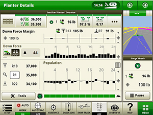 IRHD screen showing the applied downforce graph
Optional equipment on: 1775NT, 1795, DB, and Orthman custom models with MaxEmerge 5e and ExactEmerge row-units.
Crop yields have increased through the years along with the amount of residue left in the field after harvest. At the same time, tillage practices have changed, including different tillage operations which maintain large amounts of surface residue, and even no-till practices. Row cleaners are an essential tool in managing this increased amount of residue.
John Deere seeding group offers a variety of row cleaner options to meet the needs of a producer's operation. Compatibility varies by model, row spacing, and other planter equipment.
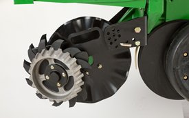
Screw-adjust, unit-mounted row cleaner
 Screw-adjust, unit-mounted row cleaner
The screw-adjust, unit-mounted row cleaner is mounted directly to the face plate of the row-unit, placing the ground engaging components just in front of the row-unit opener blades and depth gauge wheels. This close proximity allows the gauge wheels to control the depth of the row cleaner as well as the row-unit. This compact design also allows greater compatibility with fertilizer openers and other planter attachments.
SharkTooth® wheels are standard equipment on the unit-mounted row cleaner. The swept-tooth design of the wheel provides a clear path for the row-unit openers while resisting residue buildup on the wheel. The screw adjustment knob is accessible through the top of the parallel arms, providing convenient access for adjustments. The row cleaner can be adjusted in 1.6-mm (1/16-in.) increments, providing plenty of flexibility to meet the needs of changing conditions.
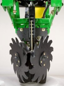
Floating row cleaner with unit-mounted coulter
 Floating row cleaner with unit-mounted coulter
The floating row cleaner allows a row cleaner to be used in conjunction with a unit-mounted coulter. This combination is often desired in heavy residue loads and reduced tillage planting conditions. The row cleaner provides a clear path for the row-unit, while the unit-mounted coulter helps penetrate tough soil conditions.
Accommodating the unit-mounted coulter means the residue wheels are farther forward from the row-unit face plate than in the case of the screw-adjust row cleaner. To maintain performance, this row cleaner has the capability to float above a defined minimum depth.
Standard depth-gauging bands on the wheels allow the row cleaner wheels to float independently of the row-unit openers, allowing both to perform in varying terrain. The unit may also be set in a fixed position by simply pinning through the bracket if desired. This row cleaner also features SharkTooth wheels as standard equipment.
The floating row cleaner and unit-mounted coulters are available on many planters as factory-installed equipment. As compatibility and details vary by model, review the following links for information on specific planter models.
NOTE: Screw-adjust row cleaners are not compatible with MaxEmerge™ 5e row-units with long parallel arms.
NOTE: DB models have the option for either unit-mounted coulter, screw-adjust row cleaners, or pneumatic row cleaners (only compatabile with MaxEmerge 5e or equipped ExactEmerge™ models). The DB60T is only available with a less row cleaner option.
SharkTooth is a trademark of Yetter Manufacturing, Inc.
RowCommand controls seed output
 RowCommand on a MaxEmerge™ 5 row-unit
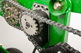 RowCommand on a chain drive MaxEmerge 5 row-unit
Controlling input costs and improving productivity are key producer requirements today. RowCommand is an effective, integrated John Deere solution designed to meet these intensifying needs. The RowCommand system manages seed output, reduces yield drag, and improves harvest capabilities on all Pro-Shaft™ driven row-units, and chain-driven MaxEmerge 5.
NOTE: Chain-drive RowCommand is only compatible with planters equipped with pneumatic downforce systems. On planters equipped with the heavy-duty downforce springs, potential chain interference may result and is not recommended.
NOTE: Chain-drive RowCommand requires some modification to brackets in order to function with corn finger pickup meters.
NOTE: Pro-Shaft drive RowCommand is compatible on MaxEmerge 5 row-units with vacuum and corn finger pickup meters. For mini-hopper row-units, RowCommand is compatible on vacuum meters only and is not compatible on corn finger pickup meters. Pro-Series™ XP row-units with corn finger pickup meters are not compatible with RowCommand.
RowCommand controls seed output by incorporating individual, low amperage clutches inside the Pro-Shaft and chain-driven gearboxes. Clutches are completely enclosed within the gearbox housing to protect them from the elements and harsh operating conditions.
When power is supplied, either manually or through John Deere Section Control software, clutches disengage the seed meters and seed flow stops. Controlling seed output at individual rows reduces overplanting in point rows and maximizes seed placement when entering/exiting headlands.
Components and operation
 Electronic power modules shown on a 1775NT Planter
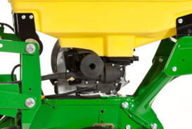 RowCommand clutch on MaxEmerge 5 with 105.7-L (3-bu) hopper
RowCommand is a simple and efficient solution to control individual row planting. This system does not utilize air to operate; therefore, no compressor, air lines, or valve modules are required.
RowCommand utilizes low-voltage controller area network (CAN) messaging to signal power to the desired clutches to stop planting or eliminates power to resume planting.
This means very little power is used in normal planting conditions, and in the event a clutch fails electrically, the meter will continue to plant.
The RowCommand system requires the following five basic components to operate:
- Electric clutches
- Electronic power modules (EPMs)
- SeedStar™ 2 monitoring (wedge box/controller)
- GreenStar™ (GS) display
- Planter wiring harnesses
Clutches are protected within the sealed Pro-Shaft and chain-driven gearboxes for years of trouble-free operation and simple installation or removal. RowCommand has true individual-row control of up to 16 clutches or sections for planters larger than 16 rows.
Unique to RowCommand, the 16 available control sections can be configured based on operator preferences. For example, on a 1775NT 24-Row Planter, every two rows can be paired together for a total of 12 control sections, or control the outermost eight rows individually and the remaining inner rows paired together for 16 control sections.
While SeedStar with RowCommand has 16 control sections, a minimum of 152.4-cm (60-in.) wide sections are recommended for optimum Swath Control Pro™ solution capabilities. As with other Swath Control Pro products, an SF2 signal is the minimum level of accuracy recommend for operation.
Pro-Shaft drive RowCommand planters
RowCommand is available as a factory-installed option or as an attachment for field conversion attachments for the following Pro-Shaft drive planter models (see chart below).
| Planter model | Row configuration |
| 1725 | 12-row narrow, 12-row wide, and 16-row narrow |
| 1725 Central Commodity System (CCS™) | 16-row narrow |
| 1765 | 12-row narrow |
| 1775 | 12-row narrow |
| 1775NT | 12 row, 16 row, and 24-row narrow |
| 1775NT CCS | 12 row, 16 row, and 24-row narrow |
| 1795 | 12/23 row, 12/24 row, 16/31 row, and 16/32 row |
| 1795 | 24 row, 50.8 cm (20 in.) |
| DB 44 | 24 row, 55.9 cm (22 in.) |
| DB 58 | 32 row, 55.9 cm (22 in.) |
| DB 60 | 36 row, 50.8 cm (20 in.) or 47 row, 38.1 cm (15 in.) |
| DB 66 | 36 row, 55.9 cm (22 in.) |
| DB 80 | 32 row, 76.2 cm (30 in.) or 48 row, 50.8 cm (20 in.) |
| DB 88 | 48 row, 55.9 cm (22 in.) |
| DB 90 | 36 row, 76.2 cm (30 in.) |
| DB 120 | 48 row, 76.2 cm (30 in.) |
| DR (Deere/Orthman™ planter) 16R40 | 16 row, 101.6 cm (40 in.) |
| DR (Deere/Orthman) 18R38 | 18 row, 96.5 cm (38 in.) |
Chain-drive RowCommand planters
In terms of planter compatibility, RowCommand for chain drive is designed for the following planter model configurations equipped with pneumatic downforce systems.
| Planter model | Row configuration |
| 1725 | 12-row narrow, 12-row wide, and 16-row narrow |
| 1765 | 12-row narrow |
| 1775 | 12-row narrow |
| 1775NT | 12 row and 16 row |
| 1775NT CCS | 12 row and 16 row |
| DB 44 | 24 row, 55.9 cm (22 in.) |
Chain-drive RowCommand and heavy-duty downforce
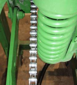 Chain interference with heavy-duty downforce
As seen in the image, chain interference may result when operating chain-drive RowCommand on planters equipped with short and long parallel arms and heavy-duty downforce springs.
NOTE: Chain-drive RowCommand is only compatible with planters equipped with pneumatic downforce systems. On planters equipped with the heavy-duty downforce springs, potential chain interference may result and is not recommended.
Chain-drive RowCommand with corn finger pickup meters
 Bracket material removal
Due to the design characteristics of the chain-drive RowCommand clutch, some modification to the corn finger pickup meter drive bracket is required. As seen in the picture to the left, some material needs to be removed from the front of the meter drive bracket in order for the chain-drive RowCommand clutch to have sufficient space for installation.
NOTE: Chain-drive RowCommand requires some modification to brackets in order to function with corn finger pickup meters.
RowCommand ordering information
To add RowCommand to a model year 2009 and newer planter model listed above is simple. Pro-Shaft drive attachments for field conversion and chain-drive attachments for field conversion are available by planter model to add the appropriate number of clutches, EPMs, brackets, hardware and row-unit harnesses. For complete installation and part detail for the RowCommand conversion, please use the RowCommand compatibility tool per specific planter model.
RowCommand is compatible and available for model year 2003 (serial number 700101) to 2008 (725101) planter models listed above. In addition to the attachment for field conversion attachment, a planter mainframe harness, SeedStar 2 controller (wedge box), and additional CAN harnesses are needed.
Integrated Swath Control Pro
Coupling RowCommand with Swath Control Pro provides the ultimate in precision planting and productivity. One company, one integrated solution are what we offer by incorporating Swath Control Pro capabilities within the SeedStar 2 wedge box (controller). Unlike previous systems, no rate controller, additional harnessing, or components are required to achieve automated individual-row control.
SeedStar 2 monitoring, RowCommand, and Swath Control Pro activation from John Deere Precision Ag Technologies are all that is needed when ordering.
System requirements
RowCommand is a simple and efficient means to control individual row planting through the use of low-voltage electric clutches. When activated, each clutch consumes no more than 0.5 amps. By design, power is only supplied to the clutch when a signal is received to stop planting. In a normal planting condition, no power is supplied and the clutch is de-energized.
Power for the RowCommand system is provided from the 9-pin ISO implement connector. All late-model 8X00 and 9X00 Series John Deere Tractors equipped with the 9-pin ISO implement connector are capable of supplying ample power for system operation.
Along with ample system power, a GreenStar display and SeedStar monitoring are required for operation and control interface. The GreenStar display is where system setup, control settings, and manual control functions are performed.
 VRD shown on a 1775NT
The seed variable-rate drive provides the ultimate planting productivity by utilizing one, two or three hydraulic motors (varies by model) to turn the seeding drive shaft. Hydraulic control of the seeding drive allows for on-the-go seeding rate changes right from the display mounted inside the tractor cab.
Combine this seeding flexibility with the map-based planting option, and seeding rates adjust automatically based on a prescription map.
Single- or dual-motor systems for variable-rate drives are available for all John Deere planters except the 1785 Rigid Frame. Dual- or three-motor drive systems are commonly used on larger (12-row and more) planters and offer the capability of half-width or three-section drive disconnect.
The VRD is available as a factory-installed option for all applicable planter models. Single- or dual-motor systems are available as field-installed attachments for most planter models; however, a three-motor VRD field-installed attachment is not available.
The seed VRD requires the SeedStar™ monitor and a radar input signal. Either tractor or planter radar may be used. Planter radar is ordered separately.
VRD offers the following advantages over common, contact-tire drive systems:
- Almost instantaneous rate changes – there is no ramp up or ramp down of system as in some competitive systems
- Permits the operator to match seed population based on different soil types or irrigation practices
- John Deere design that provides added operator safety by eliminating any possible drive creep found in some competitive variable rate drive systems
Half-width drive disconnect
The half-width drive disconnect feature is excellent for the producer concerned with controlling seed costs. This feature helps the operator place seed in the desired area and limit the amount of costly overlapped planting.
The half-width drive disconnect allows the operator to turn off half of the planter at a time for planting end rows, point rows, etc. Variable-rate-equipped planters require two drive motors to utilize the half-width disconnect feature.
 Half-width drive disconnect within frame control
With a 1765, 1765NT, and 1775 12-Row Planter, a single switch box is required for planters that are ordered with variable rate drive and half-width disconnect.
For the 1775NT, 1775NT Central Commodity System (CCS™), and 1795 Front-Folding Planters, the half-width drive disconnect switch is contained within the frame control box, conveniently located in the tractor cab. The function easily shuts off the drive for the left or right half of the planter row-unit seed meters.
Three-width drive disconnect
 Three-width drive disconnect control
Three-width drive disconnect is an option on 1725 12-Row Planters and is base equipment on the 1725 16Row30 Planter. This feature is activated by three individual console mounted switches (control box), conveniently located in the tractor cab. The function easily shuts off the planter row-unit seed meters by one-, two-, or three-drive segments independently.
 CCS
CCSCCS seed delivery adds productivity through increased seed capacity, bulk fill capability, and easy, thorough cleanout.
The two tanks have a combined capacity of 2466.7 L (70 bu) on 9.1-m (30-ft) planters and 3523.9 L (100 bu) on 12.2-m (40-ft) and larger planters. CCS tanks are manufactured using a rotomolded, polyethylene design to ensure maximum durability. The translucent tanks allow easily viewing the amount of seed in the tanks. The tanks are separated by 54.6 cm (21.5 in.) for enhanced rear visibility during transport and backing.
The following crops can be planted with CCS: corn, sweet corn, popcorn, cotton, sunflowers, sugar beets, soybeans, and sorghum (milo).
Filling the tanks is convenient due to a central filling location. The staircase and railing provide access to the filling platform between the tanks. If filling the tanks with an auger, minimum recommendations are a 15.2-cm (6-in.) diameter, 4.3-m (14-ft) auger. Each tank has an adjustable bin-level sensor to alert the operator when it is time to fill.
A standard fill light package is available on machines equipped with CCS. This feature includes two lights conveniently mounted on the railings of the machine. The lights are turned on and off with their own switch located at the bottom of the staircase.
If the seed-carrying vehicle requires hydraulic power to run the unloading system, the auxiliary hydraulic coupler option is available. These couplers are located at the bottom of the staircase and can be coupled under pressure. The system has a separate system filter that ensures the planter hydraulic system remains free of contaminates.
Seed delivery process
CCS is about reducing the time spent filling the planter with seed while maximizing the time spent planting. CCS for planters is a form of seed handling and delivery. The row-units perform the final task of seed metering and placement.
The CCS seed delivery process relies on a hydraulically-driven fan to move seed from the CCS tanks to the row-units. This fan is plumbed in to the planter's raise/lower circuit, so only one selective control valve (SCV) is needed for both functions. When the planter is lowered, lift cylinders bottom out and hydraulic flow is diverted to the seed delivery fan. A flow control valve and gauge, located near the tank, allows for the proper tank pressure setting based on seed type.
Air from the fan pressurizes the CCS tanks and delivers seed to the seed hoppers. Airflow enters the seed tanks through a nozzle in the manifold which pressurizes the tank. The air then picks up seed and moves it out the other end of the nozzle into seed delivery hoses. These hoses route the seed toward the hopper. A small amount of seed is traveling in the delivery hoses only when needed.
The hopper fills with seed until the delivery hose (discharge elbow) is covered. Once the opening is restricted, seed flow through the hose stops. Air flowing to the row-unit travels into the hopper and is the source of air for the vacuum system. This provides a much cleaner air source than previous meter designs. As the seed is picked up by the meter and planted, the seed pool shrinks until the end of the delivery hose is uncovered. At that time, the airflow and seed delivery resume and the seed pool in the hopper is replenished.
CCS tank scales for DB Planter models
The CCS tank scales for DB models are a stand-alone system from Digi-Star®. Load cells are installed at the factory and can be ordered for CCS or CCS with Refuge Plus.
There are three load cells, two at the rear of the CCS cradle and one at the front. They weigh both tanks as one; individual tank weights cannot be determined.
The load cells and display are made by Digi-Star. They are not on the controller aread network (CAN) bus system so they are not integrated into SeedStar™ software in any way. The monitor is sold separately through Digi-Star.
CCS seed cleanout
Seed cleanout could not be much easier with a CCS planter. When finished planting, any remaining seed can simply be removed via access doors at the bottom of the CCS tank.
Because seed is only traveling through the CCS delivery hoses when required by the meter, there is not much left to clean.
CCS seed delivery hoses are then purged with air from the CCS fan, and the excess seed is pushed to the individual meters. The vacuum meter door is opened and seed is removed with the supplied catch pan.
Small seed CCS components
 Manifold nozzle and nozzle with cover installed
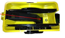 Straight seed inlet installed in mini-hopper
CCS seed delivery system increases planting productivity across the seven approved crops listed above. While highly effective delivering seed from the CCS tanks to the vacuum meters, small or light seeds (sorghum and small cotton) will require two additional components to aid in proper seed delivery.
Manifold nozzle covers (clips) should be installed to ensure seed is adequately picked up into the air stream for delivery to the row-unit. Mini-hopper discharge elbows should also be changed from the standard elbow (holes) to the small seed elbow (slotted openings) when planting sorghum (milo) and small cotton.
Digi-Star is a trademark of Digi-Star LLC.
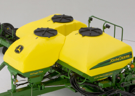
DB44, DB60, DB60T, DB66, DB80, DB88, DB90, and DB120 Planters can be equipped with the Refuge Plus option from the factory.
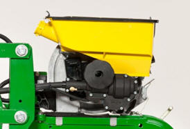
The third tank on the Refuge Plus system provides increased versatility and productivity to the planting operation by allowing the grower to plant two different varieties simultaneously. The Refuge Plus tank has manifold nozzles, or outlets, to supply seed to eight different row-units.
Refuge Plus is ideal for the grower planting Bt corn or seed corn. Refuge Plus is the solution for refuge management compliance issues associated with Bt corn production. The 881-L (25-bu) capacity of the third tank makes planting the required 20 percent refuge of non-Bt corn easier while maintaining high productivity levels of the central-fill CCS.
For example, Bt corn planted on 80 percent of the field goes into the larger CCS tanks. The required 20 percent refuge, non-Bt corn, goes into the third Refuge Plus tank with the seed hoses routed to the desired rows.
Central fill with CCS is easier for the seed-corn grower as well. The seed-corn grower can plant both male and female seed in the desired pattern simply by placing the male seed in the Refuge Plus tank, the female seed in the CCS tanks, and routing the seed delivery hoses to the desired row units.
NOTE: Only DB44, DB60, DB60T, DB66, DB80, DB88, DB90, and DB120 Planters can be equipped with the Refuge Plus option from the factory. Other CCS equipped models can add Refuge Plus through Parts.
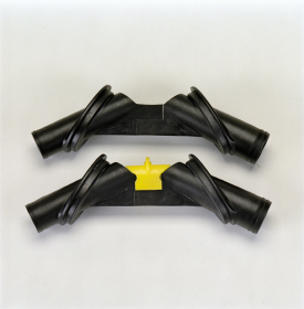
Redirecting seed delivery
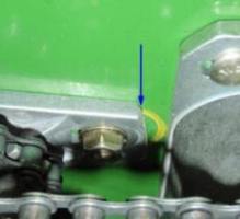
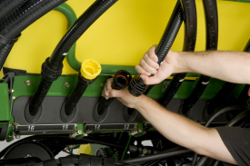 Seed delivery hose connection and yellow plug
Redirecting seed delivery from the CCS tanks to the Refuge Plus tank is fast and easy with quick-disconnect couplers. By simply disconnecting the desired CCS delivery hoses from beneath the CCS tank, capping those hoses and reconnecting the delivery lines to the Refuge Plus tank, the seed delivery source is changed.
Due to the additional weight Refuge Plus places on the planter frame, liquid fertilizer tanks are not compatible. Updated liquid insecticide tank codes have been established for Refuge Plus planters.
For increased maneuverability into narrow driveways and field approaches, the steerable axle is an option on all DB80, DB88, DB90, and DB120 models. The steerable transport axle still utilizes a pivoting rockshaft with dual lifting cylinders and combines a single steering cylinder with dual linkage assemblies. With the linked pivot points close to the centerline of each wheel, it allows a shorter cylinder stroke and smaller turn angles to translate into a tighter implement turn radius. The same 445/50R22.5 wheels are used with the steerable axle option.
The option will require an extra selective control valve (SCV), independent of all other implement functions. The option code will provide a full manually functioning axle assembly with an included in-cab display for calibrating and reading wheel angle position. The steerable axle package can be used for manual road transport functions around intersections and tight field entrances.
If desired, steerable axles can be combined with John Deere Active Implement Guidance (iSteer™ guidance and machine control system) to provide automatic planter guidance for in-field applications. The following additional components must be purchased separately from John Deere for the steerable axle to compliment Active Implement Guidance.
Components:
- iSteer tractor application controller (with activation)
- iSteer tractor harness
- StarFire™ receiver for planter
All required implement harnessing will be included in the option code. This includes the StarFire receiver harness. The receiver mast will also be provided when the option code is selected.
The purchase, installation, and calibration of the iSteer components are the responsibility of the dealership at time of predelivery.
Specifications
| Key Specs | db120-48row30-planter Current Model |
|---|---|
| Number of rows | 48 |
| Row spacing | 76.2 cm 30 in. |
| Frame - Fold configuration | Front fold |
| Frame - Flexibility | 5-section flex-frame; wing 15 degrees up and down |
| Row unit seed hoppers | Capacity Mini hoppers: 2.22 L 0.063 bu |
| Seed Meters | Base Vacuum |
| Rows and Row Spacing | |
| Number of rows | 48 |
| Row spacing | 76.2 cm 30 in. |
| Frame | |
| Fold configuration | Front fold |
| Frame tube size | 17.8x17.8 cm 7x7 in. |
| Fold-and-go from tractor cab | Base |
| Flexibility | 5-section flex-frame; wing 15 degrees up and down |
| Hitch | |
| Base | Drawbar |
| Optional | |
| Rear hitch | Optional |
| Lift System | |
| Type | Electrohydraulic series rephasing cylinder with center sec. drop axle |
| Number of cylinders | 6 |
| Tires | |
| Base | (8) 31-13.5x15 |
| Optional | |
| Quantity | 12 |
| Row Units | |
| Type | |
| Opener | |
| Depth gauging | (2) semi-pneumatic wheels: 11.4x40.6 cm 4.5x16 in. |
| Adjustment | T-handle 0.635-10.2 in. 0.25-4 in. in increments of 0.635 cm 0.25 in. |
| Walking wheels | Optional |
| Row unit seed hoppers | Capacity Mini hoppers: 2.22 L 0.063 bu Material Plastic |
| Row unit down force | Pneumatic Base, Infinitely adjustable to 181.4 kg 400 lb Base equipment |
| Scrapers, opener blades | Steel straight blade Base Heavy-duty Optional Optional |
| Seed tube sensors | Base equipment |
| Seed Meters | |
| Base | Vacuum |
| Optional | |
| Finger pickup | |
| Radial bean meter | |
| Central Commodity System | Seed capacity 4,405 L 125 bu Base |
| Drive System | |
| Base | 3-motor hydraulic variable rate drive |
| Optional | |
| Number of drive wheels | |
| Drive wheel disconnect | |
| Counter shaft | Hex: 2.22 cm 0.875 in. |
| Drill shaft | Hex: 2.22 cm 0.875 in. |
| Seed transmission | Frame-mounted |
| Transmission combinations | Electrohydraulic, on-demand adjustment |
| Markers | |
| Type | |
| Control | |
| Marker disk | |
| Shear bolt protection | |
| Less marker option | |
| Closing System | |
| Rubber tire closing system | Wheel (2) rubber tires with nylon wheel: 2.54x30.5 cm 1x12 in. Position In-line or staggered Adjustment T-handle Down force 5-position Alignment Adjustable Base equipment |
| Cast iron closing system | |
| Herbicide and Insecticide | |
| Insecticide only hopper | |
| Herbicide only hopper | |
| Insecticide and herbicide hopper | |
| Liquid Insecticide System | |
| System available | |
| Tank capacity | 1,590 L 420 gal. |
| Seed Monitor System | |
| Base | |
| Optional | |
| Tillage Attachments | |
| Unit-mounted coulter | Unit-mounted: Optional |
| Frame-mounted coulter | |
| Bubble blade | |
| .63-in. fluted blade (25 flutes) | |
| .7-in. fluted blade (13 flutes) | |
| 1-in. fluted blade (8 flutes) | |
| Row tillage support hanger | |
| Tine tooth | |
| Cons. furrower w/ leading cutout blade | |
| V-wing bed sweeps | |
| Row cleaner | |
| Row cleaner - unit-mounted coulter | |
| Row cleaner - unit-mounted DD fert. opener | |
| Fertilizer | |
| Onboard / towed / tractor tanks | |
| Tank capacity | |
| Fixed-rate application | |
| Variable-rate application | |
| Pump type | |
| Pump rate | |
| Fertilizer opener type | |
| Flow divider distribution system | |
| Pressure manifold distribution system | |
| Dry fertilizer | |
| Dimensions | |
| Transport width (with markers) | 4.6 m 15 ft |
| Transport width (without markers) | |
| Transport length | 19 m 62 ft |
| Transport height | 3.7 m 12 ft |
| Transport weight | 18,273 kg 40,200 lb |
| Transport underframe clearance | 66 cm 26 in. |
| Field operation width | |
| Field operation length | |
| Ag Management Solutions | |
| Map-based seeding | |
| Field documentation | Map-based seeding Field documentation Parallel tracking |
| Parallel tracking | |
| Additional Information | |
| Recommended tractor horsepower | |
| Recommended tractor hydraulics | |
| Warranty length | 1 year |
| Date collected |