
1765nt planter
Drawn Planter
- 8 rows on 30-in. spacing
- Available in 1.6-bu. or 3-bu. MaxEmerge™ 5 row unit
- Insecticide option for 1.6-bu.
- Rigid frame that provides narrow transport of 12 ft.
View Product Brochure
Features
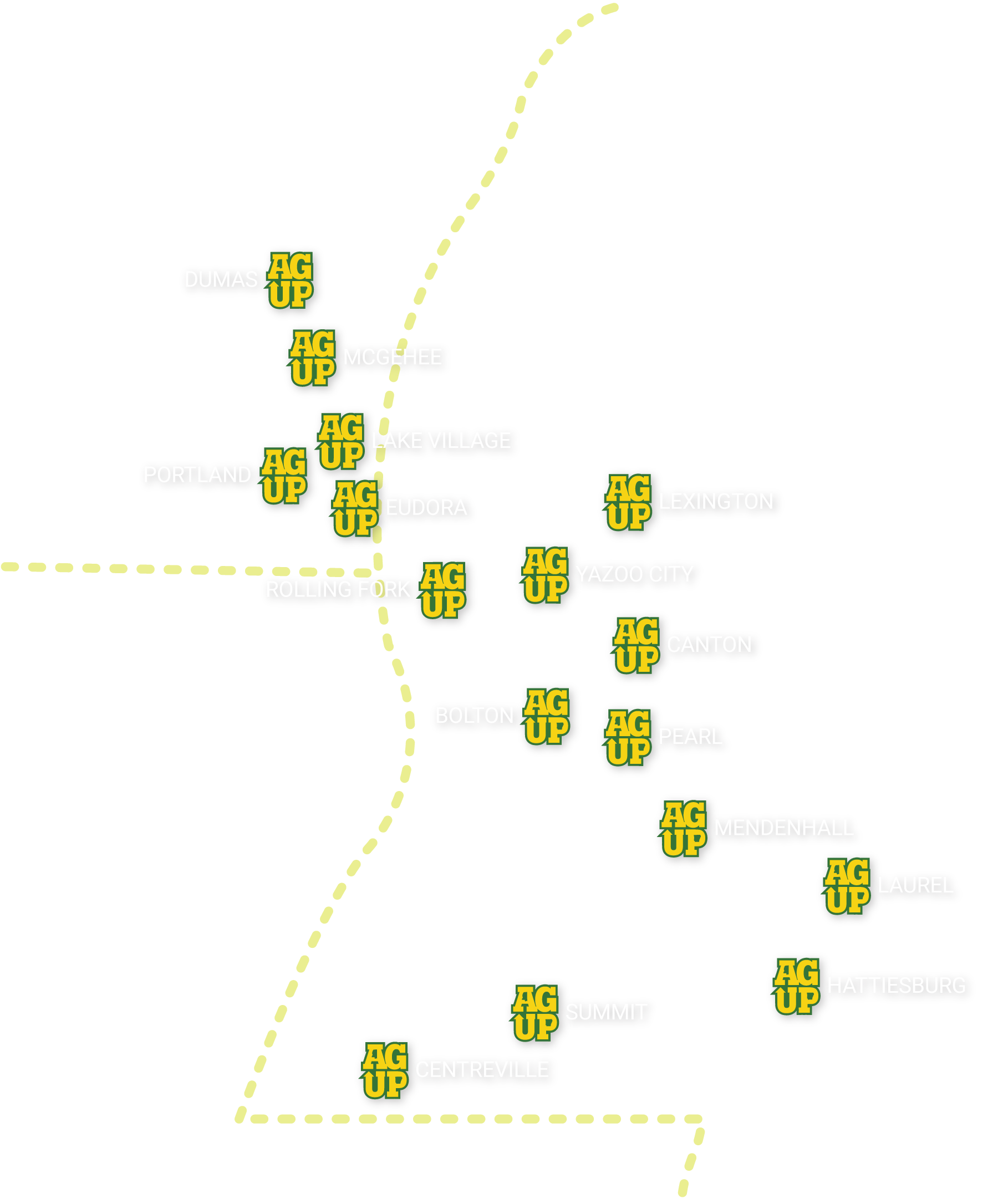
 MaxEmerge 5 with 56-L (1.6-bu) hopper plus insecticide
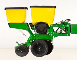
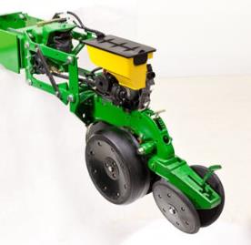 MaxEmerge 5 with mini-hopper on Central Commodity System (CCS™) machines only
The MaxEmerge family of row-units have never seen a more versatile and efficient design until the MaxEmerge 5. The 5-family row-units improve productivity, increase uptime and lower the cost of ownership like never before.
The MaxEmerge 5 row-unit was designed for improved performance and serviceability.
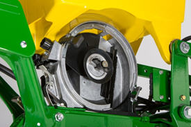
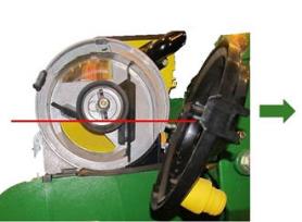
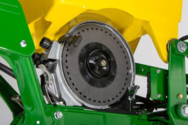
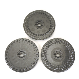
Serviceability and changing crops has always been a focus of downtime and potential seed loss. MaxEmerge XP row-units (shown on the left) are designed with the meter and hopper as one component. The frame covers the meter so that it cannot be accessed. Cleanout of excess seed requires the operator to take the entire hopper off of the row-unit and to turn it upside down. The MaxEmerge 5 meter (shown on the right) is accessible without having to remove the box. The MaxEmerge 5 design allows large hoppers to be cleaned out the same as mini-hoppers, simply by opening the meter dome and catching the seed as it falls out. This improvement allows operators to change seed varieties easier and three times faster than it took them on the previous MaxEmerge XP units and provides more uptime during the tight planting window.
 MaxEmerge 5 vacuum seed meter
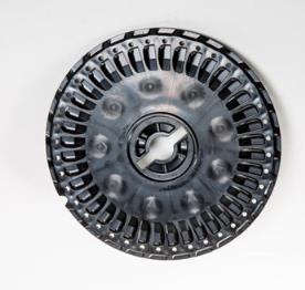
The vacuum meter system gently pulls and holds individual seeds to the holes of the seed disk for population control and spacing accuracy, equaling better crop stands and profit. Vacuum seed meters can plant a wide variety of crops and seed types by simply changing seed disks and adjusting vacuum level. Vacuum seed meters are available for planters with MaxEmerge 5 row-units.
Additional features of the vacuum seed meter include:
- One moving component (the seed metering disk) for minimum maintenance requirements
- Meter located at each row-unit for accurate seed delivery
- Good hopper seed flow characteristics for longer operating time per hopper fill
- Low airflow in meter so seed treatments are not removed
 Pro-Series™ row-unit seed pool
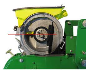 MaxEmerge 5 seed pool
The MaxEmerge 5 meter shape has also been redesigned for better seed flow. The mini-hopper design allows the planter to successfully operate on side hills up to 14 degrees.
Vacuum meter hub and latching handle
 MaxEmerge 5 vacuum meter with disk
Both the MaxEmerge 5 vacuum meters are equipped with a heavy-duty hub spring and disk latching handle. The spring ensures the seed disk stays properly positioned when operating flat-style seed disks and higher vacuum levels. Proper seed disk positioning means repeatable seed singulation, time after time. The disk-latching handle is designed for easy operation and effortless seed disk changeover. The hub is also machined to tight tolerances to further ensure alignment of metering components.
 Flat-style and cell seed disks shown
The unique cell disk design allows planting a variety of seed sizes without any additional parts or individual meter adjustments. Another advantage of cell-type seed disks is the lower vacuum requirement compared to flat-style seed disks. Lower vacuum levels mean less hydraulic demand from the tractor. Most planting conditions call for a flat disk, if you are limited in hydraulic capacity, cell disks are recommended.
Operating characteristics of vacuum seed meter
 Operating speed with seed tube technology
The vacuum seed meter is capable of operating at faster planting speeds than mechanical meters. However, planting accuracy will be influenced by seedbed conditions and the operating characteristics of the seed meter. Rough seedbeds and fast planting speeds (above 8.9 km/h [5.5 mph]) typically deteriorate seed placement accuracies when using seed tube technology.
The chart illustrates the effect operating speed has on population when using the vacuum meter. The operating band (color area) illustrates how the vacuum meter performs in relation to the desired population (indicated by horizontal line). The width of the band is due to various sizes and shapes of seeds and planting rate variations.
When operating on slopes above 15 degrees, increased or decreased population may result. To minimize this effect, reduce speed and consider using a flat style seed disk with increased vacuum level.
Vacuum meter seed disks
The ProMax 40 Flat Disk is a flat-disk planting solution field-proven to work since 1991.
The design of the ProMax 40 Flat Disk position allows seed to be released from the optimum position above the seed tube. The flush-face seed tube allows the seed to drop uninterrupted through the tube.
The ProMax 40 Flat Disk utilizes flat holes and a higher vacuum level to ensure every hole is populated with a seed. A double eliminator gently removes multiple seeds at each hole for precise population control. A knockout wheel makes certain that each hole is clear of any debris after the seed is released from the disk.
Double eliminator
For difficult to singulate seeds, a flat seed disk and double eliminator is a viable alternative to traditional cell-type seed disks. By design, a flat seed disk requires higher levels of vacuum than a cell-type disk because there is no pocket or cell to hold the seed. The higher vacuum level will pull more than one seed to the holes in the seed disk. The double eliminator is set to cover a portion of the hole in the seed disk and is the mechanism to knock multiple seeds away as the disk rotates.
Double eliminators are required with flat-type seed disks only and should not be used with cell-type seed disks. The knockout wheel is also recommended in conjunction with the double eliminator and flat seed disk to ensure seed is ejected from the disk.
Flat and celled type seed metering disks are available to allow planting a wide variety of seed types.
- Corn (field, popcorn, or sweet corn)
- Soybeans
- Cotton
- Sorghum
- Sugar beets
- Sunflowers
- Edible beans/peas
- Peanuts
- Melons, squash, cucumbers
Mini-hopper row-units, which are used only with the CCS, are compatible only with crops that the CCS is approved to plant.
- Corn
- Popcorn
- Sweet corn
- Soybeans
- Sunflowers
- Sorghum
- Cotton
NOTE: Due to small seed size and low planting populations, sugar beets can be planted with mini-hopper style meters by adding hopper extensions and not using the CCS tank. These hopper extensions can also be used for planting test plots.
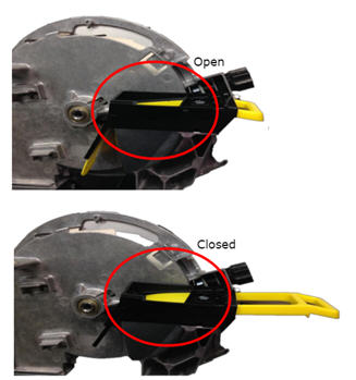 Hopper shutoff
Also, to help with meter access of 56-L and 106-L (1.6-bu and 3-bu) hoppers the hopper shutoff feature was added. With the shutoff engaged, the meter cover can be opened without first having to remove all of the seeds from the hopper. Lever down, the seed flow is on, lever horizontal and the seed flow is off.
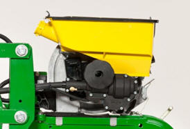
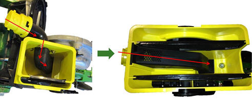 MaxEmerge 5 mini-hopper
There are significant changes to the MaxEmerge 5 mini-hopper. One update is the straight feed from the CCS hose to the mini-hopper to ensure a continuous free flow of seeds. This design change reduces the potential for plugging issues with larger seed size and the use of seed treatments. By drawing air from the CCS tank, the vacuum source is cleaner, preventing meter debris buildup.
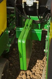
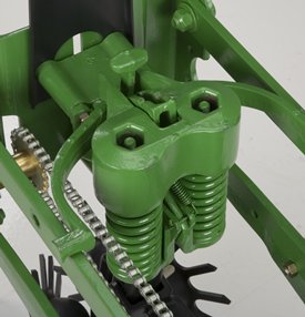
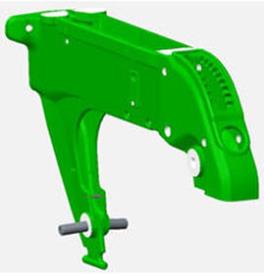 Ductile iron-cast shank
Ductile iron casting is a unique high-tech process that produces a single-piece row-unit shank this enables alignment from the seed trench to the closing wheel.
The row-unit head is also designed using the ductile iron-casting process. The row-unit head provides the mating joints between the row-unit parallel arms and the row-unit shank. It is also the upper attaching point for the seed meter and seed hopper.
Ductile iron casting of the row-unit shank and head assembly provides a row-unit that is 25 percent stronger than other competitive welded row-units.
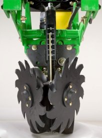
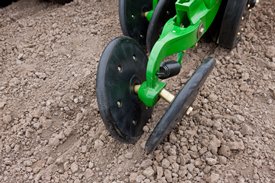
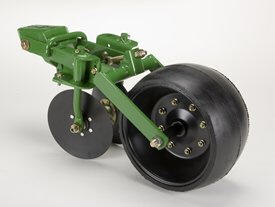
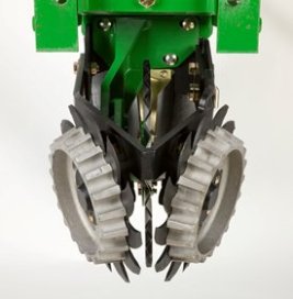
 Rubber tire closing system
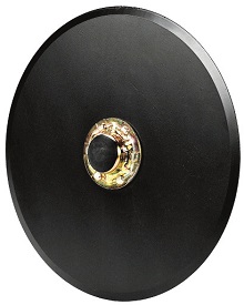
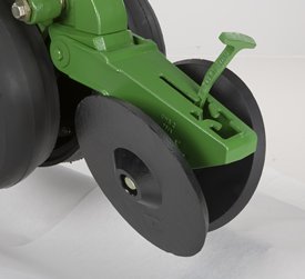 Cast wheel closing system
Rubber tire closing systems are used for most conventional, minimum-till, and no-till planting conditions. The spacing between the wheels is adjustable so the closing system can meet the needs of those who want to plant small seeds at shallow depths.
The wheels can also be staggered fore and aft to enhance residue flow. Four levels of spring force are available and are easily set with the integrated T-handle adjustment. A lower force spring can be obtained from parts, if a lower amount of force is required.
Additional closing wheel options include:
- Cast closing wheels, for tough-to-close conditions
- Disk closing, for shallow planting depths
- Closing wheel frame less wheels, for growers desiring to use aftermarket closing wheels
One of the trademark capabilities of John Deere planters has always been the ability of the Tru-Vee openers to provide an ideal seed furrow.
The thickness of the Tru-Vee opener blade is 3.5 mm (0.14 in.) this blade thickness will provide extended wear life.
The MaxEmerge 5 row-unit also provides better Tru-Vee opener bearings for longer life. The double-row ball bearing provides up to three times the wear life as the single-row bearing.
 Depth adjustment T-handle
John Deere planters provide consistent seed depth control in all field conditions. Depth control is a function of the Tru-Vee openers, the downforce system, and the gauge wheel assembly.
The gauge wheel itself is made of durable nylon composition with a concave profile. This profile gently firms the sides of the seed furrow, ensuring a well-defined trench. The shape reduces rocks and residue being picked up and thrown onto the drive chains and row-units, and helps to prevent rooster tailing of soil.
The bolt-through design utilizes an open bearing in the gauge wheel that allows an attaching bolt to pass through the wheel to the threaded hole in the gauge wheel arm. This simple bolt-through design provides for a positive attachment of the gauge wheel to the gauge wheel arm and allows quick removal of the gauge wheel for service.
Adjustability of the row-unit is critical to good performance. More available downforce options than any row unit in the industry
- Adjustable heavy-duty downforce, four settings, 0 kg (0 lb), 57 kg (125 lb), 113 kg (250 lb), and 181 kg (400 lb) of downforce
- Pneumatic downforce, infinitely variable from 0 to 181 kg (0 to 400 lb) of downforce
- Active pneumatic downforce adjusts automatically for changing ground conditions from 0 to 181 kg (0 to 400 lb) of downforce
Designed with conventional, mulch-till, and no-till planting conditions in mind
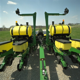
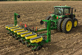 1765NT Drawn Wing-Fold Planter
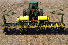 1765 12Row30 Drawn Wing-Fold Planter
Both the 1765 and 1765NT (narrow transport) feature a rugged 177.8-mm x 177.8-mm (7-in. x 7-in.) frame, wheel module lift system, and tire contact drive system. The 12Row30 flexible-frame model feature a two-section, center flexing frame design that flex 20 degrees up and 20 degrees down. The 1765 and 1765NT are recommended for conventional, mulch-till, and most no-till planting conditions.
The 1765 Planter family is available in the following frame configurations including both rigid and flex options:
- 8Row30 Narrow Transport (NT) rigid frame
- 12Row30 rigid frame
- 12Row30 flex frame
Frame functionality
 1765 Flex center frame weight bracket
For 1765 and 1765NT Wing-Fold Planters that are operating less fertilizer or would require more frame weight for tough soil conditions, additional weight can be added to the center frame. A mounting bracket and six weights add approximately 272.2 kg (600 lb) to the planter. This weight prevents the frame from flexing up in the center when planting.
Use AA41141 ballast bracket and six tractor front end weights. Attach the bracket with seven 19M7597 (M20x50) bolts and 14M7277 nuts.
Tractor attaching options
 1765 and 1765NT Planters offer one hitch length
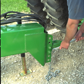 Adjustable hitch settings to match tractor height
The 1765 and 1765NT Wing-Fold Planters have one hitch length available: 373.4 cm (147 in.) for planters used with a dual-wheel-equipped tractor. The long 373.8-cm (147-in.) hitch options are available for all frame widths and can be equipped with either a clevis (code 2820) or ring (code 2810) style hitch link. Order the style of hitch link desired.
Hitches are adjustable, providing three hitch settings to match tractor drawbar height, resulting in level planter operation.
Transportability
 1765NT Planter transports at 3.7 m (12 ft)
Narrow Transport (NT) planters provide a compact transport width of only 3.7 m (12 ft).
Wing folding of all 1765 Planters is hydraulically-controlled. The independent marker option and hydraulic-fold option are plumbed together using a diverter valve (code 868A) when both options are ordered (reduces selective control valve [SCV] requirements by one).
Model | Transport width with markers | Transport height* |
8Row30 NT | 3.7 m (12 ft) | 3.3 m (10.75 ft) |
12Row30 | 4.8 m (15 ft, 8 in.) | 3.05 m (10 ft) |
| *Height measured with 18.4R-46 rear tires on tractor | ||
Fertilizer capabilities
Both the 1765 and 1765NT Planters can be equipped with a liquid fertilizer system. Eight-row configurations carry two fertilizer tanks totaling 1135.6 L (300 gal.) of capacity. The 1760 12Row30 model can handle 1703.4 L (450 gal.) of fertilizer in two tanks.
The use of the single-disk, unit-mounted injection fertilizer opener or the frame-mounted, single-disk fertilizer opener makes the 1765 and 1765NT no-till capable. The 1765 equipped with the unit-mounted, double-disk fertilizer opener is not well suited for no-till applications and opener penetration may be limited by soil conditions. Frame-mounted, single-disk fertilizer opener is only compatible with 1765NT Planters.
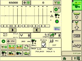
Integrated innovation is what operators will appreciate with the SeedStar 2 monitoring system and GreenStar™ 2 Display. An increasing number of acres combined with rising seed costs drive the need to easily understand planter functions and monitor performance. It is all about making every seed count and that is what SeedStar 2 delivers.
The SeedStar 2 monitoring system is a full-feature, color, seed population monitor used in conjunction with the GreenStar family of displays. SeedStar 2 is compatible with the GreenStar 2 1800 and 2600 Displays, GreenStar 3 2630 Display, the Gen 4 4200 CommandCenter™ Display, the Gen 4 4600 CommandCenter Display, the 4240 Universal Display, and the 4640 Universal Display. SeedStar 2 is not compatible with the Gen 4 Extended Monitor. Conveniently, SeedStar 2 planting functions are fully integrated with the full spectrum of Precision Ag Technology applications—guidance, coverage maps, and field documentation can be shown all on one display.
When a SeedStar 2 system is used on a planter, there is no need for a ComputerTrak™ monitor. All vital planting information is displayed in one central, easy-to-read location.
SeedStar 2 features
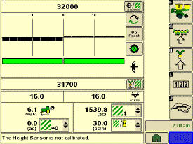 SeedStar 2 full-screen planter run page
SeedStar 2 is a user-friendly system that has retained all the valued features of SeedStar and incorporated the next generation of enhancements. For example, on-screen color indicators show drive engagement/disengagement status. In addition, three color planter-at-a-glance bars (black, orange, or red) visually inform the operator of row population status.
Not only does SeedStar 2 incorporate the use of color, it also utilizes an intuitive icon and folder based operator interface. Icons are easy to understand across many languages and reduce the need for text. Icons for planter main run page, planter setup, seed/crop setup, totals, and diagnostics are located in the soft-key region of the display. Setup is performed by selecting the appropriate icon and then choosing the tabs to enter/select information.
The SeedStar 2 monitor offers all of the features and functionality of the ComputerTrak 350 monitor and much more. SeedStar 2 monitors the following planter functions:
- Row population/spacing
- Row failure
- Average population (entire planter and by variable-rate drive [VRD] motor section)
- Vacuum level
- Fertilizer pressure
- Acre counter
- Total acreage
- Tractor speed
In addition, planter operational information is available within the SeedStar 2 monitor system. Such operational information includes population charts, seed disk vacuum settings, and setting recommendations for the piston pump liquid fertilizer system.
All SeedStar 2 systems have the capability, through a single controller, to perform both the seed monitoring and variable rate drive functions. SeedStar 2 monitoring is required for VRD population control. Even though the planter may not be equipped with SeedStar 2 VRD, the SeedStar 2 monitoring system is available and will allow for future installation of VRD.
SeedStar 2 enhancements
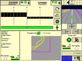 SeedStar 2 half-screen planter run page
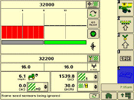 SeedStar 2 showing half-width disconnect status
The SeedStar 2 enhanced planter features include:
- GreenStar 2 display integration – eliminates the need to operate the GreenStar 2 2600 Display in the original GreenStar monitor mode or the use of dual displays.
- User-friendly, intuitive icons
- Half- or full-screen run page
- On-screen, color drive status – a quick glance at the display tells the operator if the half-width disconnect is engaged or disengaged.
- Three-color planter-at-a-glance population bar – a black bar indicates that population is close to target and within established limits; orange shows the population is above/below the alarm set point; and red signals the population is out of operating range or is not planting.
- Three-piece, color VRD indicator – each piece of the VRD gear pie turns green when the wheel motion sensor is active, planter is lowered, and drives are engaged.
SeedStar monitoring original features
SeedStar 2 retains all those SeedStar features that producers value and have come to expect:
- Planter at a glance – allows operator to view relative population levels of all rows on one screen.
- Automatic valve calibration – with the SeedStar VRD, this is now completed automatically. There is no longer a need to manually calibrate the hydraulic valves.
- Increased population updates – SeedStar will now update population levels once a second at planter start up then approximately once every three seconds.
- Mapping of actual seed rates – When combined with Field Doc™ system, actual and target seeding rates can now be mapped in APEX™ software.
- Reprogrammable utilizing controller area network (CAN) via Service ADVISOR™ diagnostics system.
- Improved diagnostics/event recorder – on SeedStar VRD planters, additional diagnostic information is available, as well as an event recorder to capture system performance data at a specific point in time.
- Ability to run motors at different population levels – on SeedStar VRD, operators running multiple motor systems can run each motor at a different speed, allowing different population levels within a planter.
- User-configurable high fertilizer pressure alarm – allows the operator to be warned when fertilizer pressure reaches a specific level.
- Automatic quick-start for SeedStar VRD – the operator no longer needs to press the quick-start button on end row turns to resume planting.
- Automatic tractor speed source selection – when equipped with an 8000/9000 Series Tractor, the system selects the radar speed or allows for manual speed input selection.
Heavy-duty adjustable downforce springs
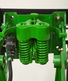 Heavy-duty adjustable downforce spring
Planter row-unit downforce is an important factor to ensure consistent and proper depth control. The heavy-duty adjustable downforce feature provides up to 181.4 kg (400 lb) of downforce. There are four settings available to allow the operator to choose the amount of downforce required for the condition: 0 kg (0 lb), 56.7 kg (125 lb), 113.4 kg (250 lb), and 181.4 kg (400 lb).
Compatibility: 1705, 1715, 1725, 1735, 1755, 1765, 1765NT, 1775 Flex, and 1785
Standard pneumatic downforce system
Pneumatic downforce provides convenient, simple adjustment of downforce for the whole planter from one location. The amount of downforce applied is infinitely adjustable from 0 to 181.4 kg (0 to 400 lb). Pneumatic downforce provides more consistent downforce throughout the range of row-unit travel than mechanical spring downforce systems.
Features include:
- 9.5-mm (3/8-in.) air delivery line instead of the 6.4-mm (1/4-in.) line used on model year 2010 and older planters.
- Air compressor assembly increased duty cycle. With this compressor, it provides a 47 percent increase in maximum air flow delivery compared to the prior air compressor.
- Pneumatic air bags with 9.5-mm (3/8-in.) air line inlets that have greater durability.
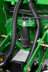 Pneumatic downforce spring
Each row-unit has a single rubber air bag located between the parallel arms. The air bags are hooked in parallel so that air can be added or released from all rows at once from one location.
The individual pneumatic downforce air bag assemblies, air compressor units, and 9.5-mm (3/8-in.) delivery lines are also available as an attachment for field conversion.
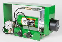 Pneumatic downforce compressor and gauge
An improved compressor is used to charge the pneumatic system. This compressor can be located on the planter frame or in the tractor cab if desired. A gauge at the compressor indicates the amount of downforce being applied.
From the factory, integral planter models with pneumatic downforce will have an improved air compressor assembly with an in-cab mounting bracket, except for the 1725 16-row and 1725 Central Commodity System (CCS™) twin-row planters, which will have the air compressor assembly mounted on the planter frame. For drawn planter models, the 1755, 1765, 1765NT, 1775 Front-Fold, and 1785 Drawn Planters will have the air compressor assembly installed either on the outer hitch or wing frame members when the pneumatic downforce system is installed.
Base equipment on: 1705, 1715, 1725, 1735, 1755, 1765, 1765NT, 1775 and 1785.
Integrated pneumatic downforce system
The functional features of the integrated system are the same as the standard pneumatic system, explained above, with the addition of control through the GreenStar™ display.
System control with the GreenStar display
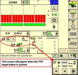 Pneumatic downforce control in GreenStar 2 Display
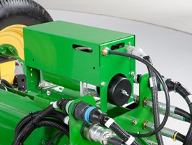 Air compressor mounted on 1775NT outer hitch
On 1725 16-row, 1725 CCS TR, 1775NT, 1775NT CCS, 1795, DR, and DB Series Planter models, the air compressor will be mounted on the outer hitch or frame assembly. Since the air compressor assembly is mounted on the outer hitch (as noted in the picture above) or frame, adjustments for row-unit downforce and related system pressures will be made electronically with the GreenStar display.
When adjusting the amount of row-unit downforce using the GreenStar display, the operator will select the amount of downforce (kg [lb]) to be applied across the planter. Depending on the soil conditions at hand, the operator might need to adjust the relative amount of row-unit downforce being applied during the planting operation. The integrated pneumatic downforce controls within the GreenStar display will only allow for set-point operation and not automatic control as the planter is operating in different soil conditions. The pneumatic downforce system does not have the capability to automatically adjust downforce.
On-board air storage
 Onboard air storage installed on 1775NT 24R30
The 1725 16-row, 1725 CCS TR, 1775NT, 1775NT CCS, 1795, DR, and DB Series planters will have onboard air storage to increase the overall response time when making a row-unit downforce adjustment from the GreenStar display. The onboard air storage is comprised of a 18.9-L (5-gal.) storage tank with valve assembly.
Base equipment on: 1725 CCS, 1725 16-row, 1725T, 1775NT, 1775NT CCS, 1795, DR, and DB Series Planters with MaxEmerge™ 5 row-units. MaxEmerge 5e and ExactEmerge™ equipped planters come with active pneumatic downforce in base.
Active pneumatic downforce
 Active downforce compressor assembly
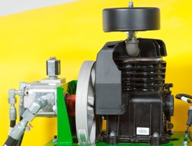 Hydraulic motor
A hydraulically driven compressor works with the SeedStar™ 3 HP system and SeedStar XP system to automate downforce control. Just set the row-unit target margin value and the active pneumatic downforce system works automatically. The system will make sure the planter maintains this value, achieving precise soil penetration, and consistent planting depth, without sidewall soil compaction. From the factory, the system is set at 45.4 kg (100 lb) target downforce margin, but may be modified for varying field conditions. This frees the operator from constantly making manual downforce adjustments as conditions change.
This system offers a split-rank control feature for 1795 and DB Split-Row Planters. On split-row planters, active downforce will control the front and rear rows independently. This compensates for differing downforce requirements between the ranks that can be caused by things like different tillage or insecticide attachments and will help maintain an accurate planting depth and consistent margin across all the rows.
Active pneumatic downforce is available as factory installed or as an attachment for field conversion.
SeedStar XP row-unit downforce planter run page
 SeedStar XP downforce planter run page
Active downforce control is integrated into SeedStar XP and SeedStar 3 HP monitoring systems.
Margin is the amount of weight riding on the depth gauge wheels that ensures desired firming of the seedbed as set by the operator.
Once a target margin has been defined, enter the value into SeedStar XP or SeedStar 3 HP and let active downforce do the rest. The system will actively adjust the air pressure in the air bags to maintain a constant margin across the planter. The changes in air pressure will change the amount of downforce placed on the row-unit, compensating and reacting for varying conditions through the field whether it is different tillage practices, soil types, or moisture.
 Downforce and margin example
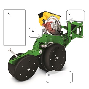
- A - Margin – amount of additional downforce applied to a row-unit above and beyond what is required for penetration to achieve planting depth. This additional weight will ride on the depth gauge wheels. 54.4 kg (120 lb) + 36.3 kg (80 lb) = 90.7 kg (200 lb) – 68 kg (150 lb) = 22.7 kg (50 lb) of margin
- B - Weight of row-unit - 54.4 kg (120 lb)
- C - Downforce – force that is applied to the row-unit by the air bag circuit - 36.3 kg (80 lb)
- D - Resistance from soil - 68 kg (150 lb)
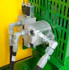
Hydraulically driven compressor
 Hydraulic motor
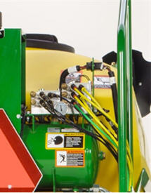 Pneumatic valve
The hydraulically driven air compressor can deliver up to eight times the air flow, allowing for more and faster downforce changes to be made. This more robust design features a 37.8-L (10-gal.) storage tank across all models with active downforce.
At approximately 15.1 L/min (4 gpm), hydraulic demands are low and ties into the machine’s lift and CCS hydraulic circuit so it does not require any additional selective control valves (SCVs). The SeedStar XP and SeedStar 3 HP monitoring systems work with the compressor and valve assembly to regulate air to downforce springs, enabling the active control.
Another feature of John Deere active downforce is the ability for the pneumatic valve to independently control split-rank machines. This system senses the downforce needs from the front and rear ranks separately and independently adjusts air pressures with the dual-rank pneumatic valve when equipped. Active pneumatic downforce requires SeedStar XP or SeedStar 3 HP to enable active control.
Base equipment on: All MaxEmerge 5e and ExactEmerge equipped planter models.
Individual row hydraulic downforce (IRHD)
IRHD has been specifically designed to meet the needs of producers that are looking to adjust to the toughest field conditions and provide maximum yield potential from field to field, season after season. IRHD works as a closed-loop downforce system that reacts quickly on an individual row basis to changing soil conditions supporting increased ground contact, which can lead to improved seed depth consistency. When setting planter downforce margin, the system will apply the needed downforce by row to maintain ground contact. From the factory, the margin will be set at 45.4 kg (100 lb), changes may be required based on varying field conditions.
The system allows operators to maintain gauge wheel ground contact leading to desired seed depth placement. IRHD can adjust five times per second and make adjustments of 45.4 kg (100 lb) in less than a second. The system has a total range of applied downforce from 22.7 kg (50 lb) to 204.1 kg (450 lb) and utilizes the power beyond circuit on the tractor. IRHD is 58 percent faster than the active pneumatic downforce solution. Fast reaction and increased ground contact can lead to improved emergence. With uniform emergence, some studies have shown a yield impact from 5 percent to 9 percent.
IRHD is controlled through the Gen 4 4600 CommandCenter™ Display or 4640 Universal Display with SeedStar 4HP. As shown below, operators can view ground contact or applied downforce using the toggle button.
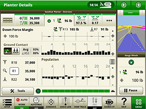 IRHD screen showing the ground contact graph
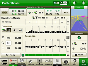 IRHD screen showing the applied downforce graph
Optional equipment on: 1775NT, 1795, DB, and Orthman custom models with MaxEmerge 5e and ExactEmerge row-units.
RowCommand controls seed output
 RowCommand on a MaxEmerge™ 5 row-unit
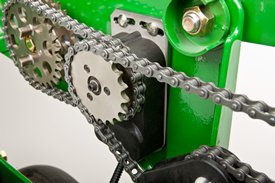 RowCommand on a chain drive MaxEmerge 5 row-unit
Controlling input costs and improving productivity are key producer requirements today. RowCommand is an effective, integrated John Deere solution designed to meet these intensifying needs. The RowCommand system manages seed output, reduces yield drag, and improves harvest capabilities on all Pro-Shaft™ driven row-units, and chain-driven MaxEmerge 5.
NOTE: Chain-drive RowCommand is only compatible with planters equipped with pneumatic downforce systems. On planters equipped with the heavy-duty downforce springs, potential chain interference may result and is not recommended.
NOTE: Chain-drive RowCommand requires some modification to brackets in order to function with corn finger pickup meters.
NOTE: Pro-Shaft drive RowCommand is compatible on MaxEmerge 5 row-units with vacuum and corn finger pickup meters. For mini-hopper row-units, RowCommand is compatible on vacuum meters only and is not compatible on corn finger pickup meters. Pro-Series™ XP row-units with corn finger pickup meters are not compatible with RowCommand.
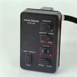
RowCommand controls seed output by incorporating individual, low amperage clutches inside the Pro-Shaft and chain-driven gearboxes. Clutches are completely enclosed within the gearbox housing to protect them from the elements and harsh operating conditions.
When power is supplied, either manually or through John Deere Section Control software, clutches disengage the seed meters and seed flow stops. Controlling seed output at individual rows reduces overplanting in point rows and maximizes seed placement when entering/exiting headlands.
Components and operation
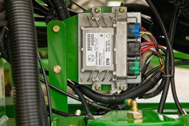 Electronic power modules shown on a 1775NT Planter
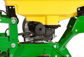 RowCommand clutch on MaxEmerge 5 with 105.7-L (3-bu) hopper
RowCommand is a simple and efficient solution to control individual row planting. This system does not utilize air to operate; therefore, no compressor, air lines, or valve modules are required.
RowCommand utilizes low-voltage controller area network (CAN) messaging to signal power to the desired clutches to stop planting or eliminates power to resume planting.
This means very little power is used in normal planting conditions, and in the event a clutch fails electrically, the meter will continue to plant.
The RowCommand system requires the following five basic components to operate:
- Electric clutches
- Electronic power modules (EPMs)
- SeedStar™ 2 monitoring (wedge box/controller)
- GreenStar™ (GS) display
- Planter wiring harnesses
Clutches are protected within the sealed Pro-Shaft and chain-driven gearboxes for years of trouble-free operation and simple installation or removal. RowCommand has true individual-row control of up to 16 clutches or sections for planters larger than 16 rows.
Unique to RowCommand, the 16 available control sections can be configured based on operator preferences. For example, on a 1775NT 24-Row Planter, every two rows can be paired together for a total of 12 control sections, or control the outermost eight rows individually and the remaining inner rows paired together for 16 control sections.
While SeedStar with RowCommand has 16 control sections, a minimum of 152.4-cm (60-in.) wide sections are recommended for optimum Swath Control Pro™ solution capabilities. As with other Swath Control Pro products, an SF2 signal is the minimum level of accuracy recommend for operation.
Pro-Shaft drive RowCommand planters
RowCommand is available as a factory-installed option or as an attachment for field conversion attachments for the following Pro-Shaft drive planter models (see chart below).
| Planter model | Row configuration |
| 1725 | 12-row narrow, 12-row wide, and 16-row narrow |
| 1725 Central Commodity System (CCS™) | 16-row narrow |
| 1765 | 12-row narrow |
| 1775 | 12-row narrow |
| 1775NT | 12 row, 16 row, and 24-row narrow |
| 1775NT CCS | 12 row, 16 row, and 24-row narrow |
| 1795 | 12/23 row, 12/24 row, 16/31 row, and 16/32 row |
| 1795 | 24 row, 50.8 cm (20 in.) |
| DB 44 | 24 row, 55.9 cm (22 in.) |
| DB 58 | 32 row, 55.9 cm (22 in.) |
| DB 60 | 36 row, 50.8 cm (20 in.) or 47 row, 38.1 cm (15 in.) |
| DB 66 | 36 row, 55.9 cm (22 in.) |
| DB 80 | 32 row, 76.2 cm (30 in.) or 48 row, 50.8 cm (20 in.) |
| DB 88 | 48 row, 55.9 cm (22 in.) |
| DB 90 | 36 row, 76.2 cm (30 in.) |
| DB 120 | 48 row, 76.2 cm (30 in.) |
| DR (Deere/Orthman™ planter) 16R40 | 16 row, 101.6 cm (40 in.) |
| DR (Deere/Orthman) 18R38 | 18 row, 96.5 cm (38 in.) |
Chain-drive RowCommand planters
In terms of planter compatibility, RowCommand for chain drive is designed for the following planter model configurations equipped with pneumatic downforce systems.
| Planter model | Row configuration |
| 1725 | 12-row narrow, 12-row wide, and 16-row narrow |
| 1765 | 12-row narrow |
| 1775 | 12-row narrow |
| 1775NT | 12 row and 16 row |
| 1775NT CCS | 12 row and 16 row |
| DB 44 | 24 row, 55.9 cm (22 in.) |
Chain-drive RowCommand and heavy-duty downforce
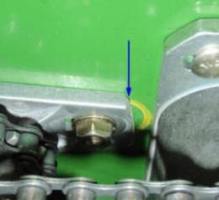
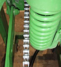 Chain interference with heavy-duty downforce
As seen in the image, chain interference may result when operating chain-drive RowCommand on planters equipped with short and long parallel arms and heavy-duty downforce springs.
NOTE: Chain-drive RowCommand is only compatible with planters equipped with pneumatic downforce systems. On planters equipped with the heavy-duty downforce springs, potential chain interference may result and is not recommended.
Chain-drive RowCommand with corn finger pickup meters
 Bracket material removal
Due to the design characteristics of the chain-drive RowCommand clutch, some modification to the corn finger pickup meter drive bracket is required. As seen in the picture to the left, some material needs to be removed from the front of the meter drive bracket in order for the chain-drive RowCommand clutch to have sufficient space for installation.
NOTE: Chain-drive RowCommand requires some modification to brackets in order to function with corn finger pickup meters.
RowCommand ordering information
To add RowCommand to a model year 2009 and newer planter model listed above is simple. Pro-Shaft drive attachments for field conversion and chain-drive attachments for field conversion are available by planter model to add the appropriate number of clutches, EPMs, brackets, hardware and row-unit harnesses. For complete installation and part detail for the RowCommand conversion, please use the RowCommand compatibility tool per specific planter model.
RowCommand is compatible and available for model year 2003 (serial number 700101) to 2008 (725101) planter models listed above. In addition to the attachment for field conversion attachment, a planter mainframe harness, SeedStar 2 controller (wedge box), and additional CAN harnesses are needed.
Integrated Swath Control Pro
Coupling RowCommand with Swath Control Pro provides the ultimate in precision planting and productivity. One company, one integrated solution are what we offer by incorporating Swath Control Pro capabilities within the SeedStar 2 wedge box (controller). Unlike previous systems, no rate controller, additional harnessing, or components are required to achieve automated individual-row control.
SeedStar 2 monitoring, RowCommand, and Swath Control Pro activation from John Deere Precision Ag Technologies are all that is needed when ordering.
System requirements
RowCommand is a simple and efficient means to control individual row planting through the use of low-voltage electric clutches. When activated, each clutch consumes no more than 0.5 amps. By design, power is only supplied to the clutch when a signal is received to stop planting. In a normal planting condition, no power is supplied and the clutch is de-energized.
Power for the RowCommand system is provided from the 9-pin ISO implement connector. All late-model 8X00 and 9X00 Series John Deere Tractors equipped with the 9-pin ISO implement connector are capable of supplying ample power for system operation.
Along with ample system power, a GreenStar display and SeedStar monitoring are required for operation and control interface. The GreenStar display is where system setup, control settings, and manual control functions are performed.
Seed variable-rate drive provides the ultimate planting productivity by utilizing one, two, or three hydraulic motors (varies by model) to turn the seeding drive shaft. Hydraulic control of the seeding drive allows for on-the-go seeding rate changes right from the display mounted inside the tractor cab. Combine this seeding flexibility with the map-based planting option, and seeding rates adjust automatically based on the prescribed map.
Variable-rate drive offers the following advantages over common, ground, or contact-tire drive systems:
- Rate changes are almost instantaneous; no ramp up or ramp down of system as in some competitive systems
- Permits the producer to match seed population based on different soil types or irrigation practices
- John Deere design provides added operator safety by eliminating any possible drive creep found in some competitive variable-rate drive systems
 1755 equipped with variable-rate drive
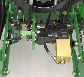
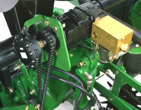 1765NT equipped with variable-rate drive
Single- or dual-motor systems for variable-rate drives are available for all John Deere planters except the 1785 Rigid Frame. Variable-rate drive is available as a factory-installed option for all applicable planter models.
Single- or dual-motor systems are available as field-installed attachments for most planter models; however, a three-motor variable-rate drive field-installed attachment is not available.
Seed variable-rate drive requires the SeedStar™ monitor and a radar input signal. Either tractor or planter radar may be used. Planter radar is ordered separately.
NOTE: Peanut seed meter disks require the variable-drive transmission.
 VRD shown on a 1775NT
The seed variable-rate drive provides the ultimate planting productivity by utilizing one, two or three hydraulic motors (varies by model) to turn the seeding drive shaft. Hydraulic control of the seeding drive allows for on-the-go seeding rate changes right from the display mounted inside the tractor cab.
Combine this seeding flexibility with the map-based planting option, and seeding rates adjust automatically based on a prescription map.
Single- or dual-motor systems for variable-rate drives are available for all John Deere planters except the 1785 Rigid Frame. Dual- or three-motor drive systems are commonly used on larger (12-row and more) planters and offer the capability of half-width or three-section drive disconnect.
The VRD is available as a factory-installed option for all applicable planter models. Single- or dual-motor systems are available as field-installed attachments for most planter models; however, a three-motor VRD field-installed attachment is not available.
The seed VRD requires the SeedStar™ monitor and a radar input signal. Either tractor or planter radar may be used. Planter radar is ordered separately.
VRD offers the following advantages over common, contact-tire drive systems:
- Almost instantaneous rate changes – there is no ramp up or ramp down of system as in some competitive systems
- Permits the operator to match seed population based on different soil types or irrigation practices
- John Deere design that provides added operator safety by eliminating any possible drive creep found in some competitive variable rate drive systems
Half-width drive disconnect
The half-width drive disconnect feature is excellent for the producer concerned with controlling seed costs. This feature helps the operator place seed in the desired area and limit the amount of costly overlapped planting.
The half-width drive disconnect allows the operator to turn off half of the planter at a time for planting end rows, point rows, etc. Variable-rate-equipped planters require two drive motors to utilize the half-width disconnect feature.
 Half-width drive disconnect within frame control
With a 1765, 1765NT, and 1775 12-Row Planter, a single switch box is required for planters that are ordered with variable rate drive and half-width disconnect.
For the 1775NT, 1775NT Central Commodity System (CCS™), and 1795 Front-Folding Planters, the half-width drive disconnect switch is contained within the frame control box, conveniently located in the tractor cab. The function easily shuts off the drive for the left or right half of the planter row-unit seed meters.
Three-width drive disconnect
 Three-width drive disconnect control
Three-width drive disconnect is an option on 1725 12-Row Planters and is base equipment on the 1725 16Row30 Planter. This feature is activated by three individual console mounted switches (control box), conveniently located in the tractor cab. The function easily shuts off the planter row-unit seed meters by one-, two-, or three-drive segments independently.
Crop yields have increased through the years along with the amount of residue left in the field after harvest. At the same time, tillage practices have changed, including different tillage operations which maintain large amounts of surface residue, and even no-till practices. Row cleaners are an essential tool in managing this increased amount of residue.
John Deere seeding group offers a variety of row cleaner options to meet the needs of a producer's operation. Compatibility varies by model, row spacing, and other planter equipment.
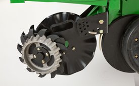
Screw-adjust, unit-mounted row cleaner
 Screw-adjust, unit-mounted row cleaner
The screw-adjust, unit-mounted row cleaner is mounted directly to the face plate of the row-unit, placing the ground engaging components just in front of the row-unit opener blades and depth gauge wheels. This close proximity allows the gauge wheels to control the depth of the row cleaner as well as the row-unit. This compact design also allows greater compatibility with fertilizer openers and other planter attachments.
SharkTooth® wheels are standard equipment on the unit-mounted row cleaner. The swept-tooth design of the wheel provides a clear path for the row-unit openers while resisting residue buildup on the wheel. The screw adjustment knob is accessible through the top of the parallel arms, providing convenient access for adjustments. The row cleaner can be adjusted in 1.6-mm (1/16-in.) increments, providing plenty of flexibility to meet the needs of changing conditions.
Floating row cleaner with unit-mounted coulter
 Floating row cleaner with unit-mounted coulter
The floating row cleaner allows a row cleaner to be used in conjunction with a unit-mounted coulter. This combination is often desired in heavy residue loads and reduced tillage planting conditions. The row cleaner provides a clear path for the row-unit, while the unit-mounted coulter helps penetrate tough soil conditions.
Accommodating the unit-mounted coulter means the residue wheels are farther forward from the row-unit face plate than in the case of the screw-adjust row cleaner. To maintain performance, this row cleaner has the capability to float above a defined minimum depth.
Standard depth-gauging bands on the wheels allow the row cleaner wheels to float independently of the row-unit openers, allowing both to perform in varying terrain. The unit may also be set in a fixed position by simply pinning through the bracket if desired. This row cleaner also features SharkTooth wheels as standard equipment.
The floating row cleaner and unit-mounted coulters are available on many planters as factory-installed equipment. As compatibility and details vary by model, review the following links for information on specific planter models.
NOTE: Screw-adjust row cleaners are not compatible with MaxEmerge™ 5e row-units with long parallel arms.
NOTE: DB models have the option for either unit-mounted coulter, screw-adjust row cleaners, or pneumatic row cleaners (only compatabile with MaxEmerge 5e or equipped ExactEmerge™ models). The DB60T is only available with a less row cleaner option.
SharkTooth is a trademark of Yetter Manufacturing, Inc.
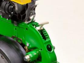
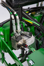
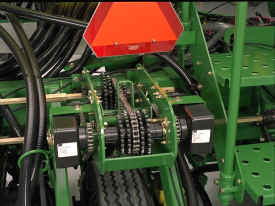
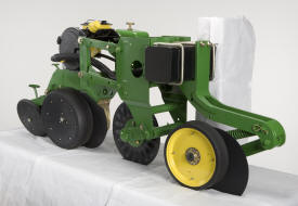
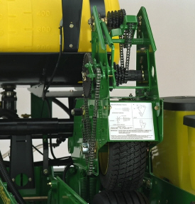 1765NT tire contact drive system
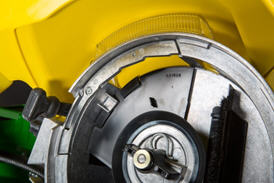
The tire contact drive for mechanical seed transmissions is a great fit for the mid-to-large planter operator concerned with quick transport capabilities, lower maintenance, and positive seed meter drives. The tire contact drive system is a simple, reliable, and efficient way to power seed transmission and meters.
The tire contact system drives the seed transmission mounted above the inner planter ground drive tire. A turf tire engages the ground drive tire when the planter is lowered, automatically turning the seed transmission and seed meters. Automatic drive disconnect occurs when the planter is raised and the turf tire separates from the ground-engaging tire. The system eliminates clutches, countershafts, and manual transport disconnects needed on direct ground drive systems. Drive chains and sprockets are moved up and out of the soil and residue zone for excellent reliability.
Tire contact drive systems are base equipment on the 1765, 1765NT, 1775 12-Row, and 1785 Planters. Contact between the ground-engaging tire and seed transmission tire is positive. On all models mentioned, a spring set applies downforce of the turf tire assembly onto the ground-engaging tire. System slippage is also minimized because the planter drive tires track in the tractor tire tracks. Frame designs differ (such as tire width) and the following different downforce requirements exist:
- 1765 8-Row drives have 207.3 kg (457 lb) of downforce.
- 1765 and 1775 12-Row drives have 254 kg (560 lb) of downforce.
The 1765 model uses one rear-mounted seed transmission. However, if the planter also has the fertilizer option, there is another rear-mounted transmission for the fertilizer drive. The 1785 Rigid Planters utilize one front-mounted seed transmission and if the planter is equipped with the liquid fertilizer option, another front-mounted transmission is utilized. The 1775 12-Row Planter utilizes two rear-mounted seed transmissions. Another rear-mounted transmission is used if the planter has the fertilizer option.
Specifications
| Key Specs | 1765nt-planter Current Model |
|---|---|
| Number of rows | 8 or 12 |
| Row spacing | 8-Row Narrow: 760 mm 30 in. 12-Row Narrow: 760 mm |
| Frame - Fold configuration | |
| Frame - Flexibility | |
| Row unit seed hoppers | Capacity 58 or 106 L 1.6 or 3 bu |
| Seed Meters | Base Plateless, finger pickup, or vacuum meter |
| Rows and Row Spacing | |
| Number of rows | 8 or 12 |
| Row spacing | 8-Row Narrow: 760 mm 30 in. 12-Row Narrow: 760 mm |
| Frame | |
| Fold configuration | |
| Frame tube size | |
| Fold-and-go from tractor cab | |
| Flexibility | |
| Hitch | |
| Base | |
| Optional | |
| Rear hitch | |
| Lift System | |
| Type | Wheel modules with hydraulic cylinders |
| Number of cylinders | |
| Tires | |
| Base | 16 x 6.5 8PR Seed Drive Tires 9.5L-15 8PR Rib Implement Tires |
| Optional | |
| Quantity | |
| Row Units | |
| Type | MaxEmerge™ 5 row units |
| Opener | Tru-Vee Double Disk |
| Depth gauging | |
| Adjustment | |
| Walking wheels | |
| Row unit seed hoppers | Capacity 58 or 106 L 1.6 or 3 bu |
| Row unit down force | |
| Scrapers, opener blades | |
| Seed tube sensors | |
| Seed Meters | |
| Base | Plateless, finger pickup, or vacuum meter |
| Optional | |
| Finger pickup | |
| Radial bean meter | |
| Central Commodity System | |
| Drive System | |
| Base | Sprocket and chain from drive wheels or Hydraulic variable rate drive |
| Optional | |
| Number of drive wheels | |
| Drive wheel disconnect | |
| Counter shaft | |
| Drill shaft | |
| Seed transmission | |
| Transmission combinations | |
| Markers | |
| Type | Automatic alternating or independent control |
| Control | |
| Marker disk | |
| Shear bolt protection | |
| Less marker option | |
| Closing System | |
| Rubber tire closing system | |
| Cast iron closing system | |
| Herbicide and Insecticide | |
| Insecticide only hopper | |
| Herbicide only hopper | |
| Insecticide and herbicide hopper | |
| Liquid Insecticide System | |
| System available | |
| Tank capacity | |
| Seed Monitor System | |
| Base | |
| Optional | |
| Tillage Attachments | |
| Unit-mounted coulter | |
| Frame-mounted coulter | |
| Bubble blade | |
| .63-in. fluted blade (25 flutes) | |
| .7-in. fluted blade (13 flutes) | |
| 1-in. fluted blade (8 flutes) | |
| Row tillage support hanger | |
| Tine tooth | |
| Cons. furrower w/ leading cutout blade | |
| V-wing bed sweeps | |
| Row cleaner | |
| Row cleaner - unit-mounted coulter | |
| Row cleaner - unit-mounted DD fert. opener | |
| Fertilizer | |
| Onboard / towed / tractor tanks | |
| Tank capacity | |
| Fixed-rate application | |
| Variable-rate application | |
| Pump type | |
| Pump rate | |
| Fertilizer opener type | |
| Flow divider distribution system | |
| Pressure manifold distribution system | |
| Dry fertilizer | |
| Dimensions | |
| Transport width (with markers) | 8-Row: 3630 mm 11.92 ft 12-Row: 4775 mm 15.67 ft |
| Transport width (without markers) | |
| Transport length | |
| Transport height | 8-Row: 3284 mm 10.75 ft 12-Row: 3429 mm 11.25 ft |
| Transport weight | Average frame weight: 4410 kg 9720 lb |
| Transport underframe clearance | |
| Field operation width | 8-Row: 6540 mm 21.42 ft 12-Row: 8811 mm 28.92 ft |
| Field operation length | Short hitch: 8-Row: 4647 mm 15.25 ft 12-Row: 4647 mm Long hitch: 8-Row: 5406 mm 17.75 ft 12-Row: 5406 mm |
| Ag Management Solutions | |
| Map-based seeding | |
| Field documentation | |
| Parallel tracking | |
| Additional Information | |
| Recommended tractor horsepower | |
| Recommended tractor hydraulics | |
| Warranty length | |
| Date collected |
Accessories and Attachments
Down Force
Upforce / Downforce spring systems
Planter row-unit downforce is an important factor to ensure consistent and proper depth control. Downforce systems are used to keep the planting units from bouncing on rough seedbeds and to improve planter penetration in heavy residue and harder soil conditions. The amount of downforce required is determined by how the planter is equipped and the field conditions in which the planter is used.
Non-adjustable springs can also be used to apply upforce on the row-units. Upforce can be achieved by changing the orientation of the spring on the parallel arms. This upforce can be used to counteract excess
row-unit margin or extra weight cause by seed, tillage, or other attachments on the row-unit. Upforce springs will limit the maximum amount of downforce that can be place on a row-unit by the downforce system and should only be used in conditions were adequate and consistent depth control is easily maintained.
Non-adjustable springs in the upforce or downforce position can also be used to counteract variances in row to row. When used in conjunction with the pneumatic downforce system, non-adjustable springs can be used to provide a more consistent row-unit margin on each row by compensating for inconsistencies such as tire tracks, different row-unit tillage attachments, and other various attachments.
Non-adjustable springs
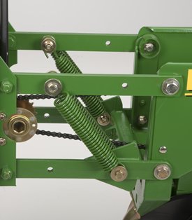 Non-adjustable springs, row-unit upforce
A single set of springs apply approximately 90 lb of upforce / downforce per row. Two sets of springs can be used for 180 lb of force per row.
Non-adjustable downforce springs are recommended for use in conventional tilled soil for planting speeds over 5 mph and/or in rough-tilled seedbed conditions. Non-adjustable springs can be used with tillage attachments in lighter, conventional tilled soils. (Not recommended for use with unit- or frame-mounted coulter.)
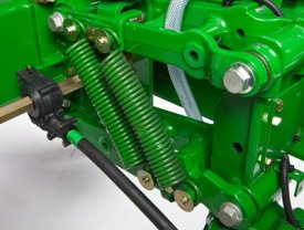 Dual upforce springs 1700 TR
Adjustable heavy-duty springs
 Adjustable, heavy-duty downforce springs
Adjustable, heavy-duty downforce can be used to apply 0 lb to 400 lb of downforce per row and has four settings: 0 lb, 125 lb, 250 lb, and 400 lb. The adjustable, heavy-duty downforce system can be used in all planting conditions and is compatible with all tillage attachments (recommended with unit-mounted coulter, row cleaners, and unit-mounted double-disk fertilizer openers in conservation planting conditions).
- NOTE: Compatible with all MaxEmerge™ Plus planters. Vacuum planters built prior to June 1992 require updated manifold brackets (A52970) to eliminate adjustment interference.
Upforce / Downforce spring systems
Planter row-unit downforce is an important factor to ensure consistent and proper depth control. Downforce systems are used to keep the planting units from bouncing on rough seedbeds and to improve planter penetration in heavy residue and harder soil conditions. The amount of downforce required is determined by how the planter is equipped and the field conditions in which the planter is used.
Non-adjustable springs can also be used to apply upforce on the row-units. Upforce can be achieved by changing the orientation of the spring on the parallel arms. This upforce can be used to counteract excess
row-unit margin or extra weight cause by seed, tillage, or other attachments on the row-unit. Upforce springs will limit the maximum amount of downforce that can be place on a row-unit by the downforce system and should only be used in conditions were adequate and consistent depth control is easily maintained.
Non-adjustable springs in the upforce or downforce position can also be used to counteract variances in row to row. When used in conjunction with the pneumatic downforce system, non-adjustable springs can be used to provide a more consistent row-unit margin on each row by compensating for inconsistencies such as tire tracks, different row-unit tillage attachments, and other various attachments.
Non-adjustable springs
Non-adjustable springs, row-unit upforceA single set of springs apply approximately 90 lb of upforce / downforce per row. Two sets of springs can be used for 180 lb of force per row.
Non-adjustable downforce springs are recommended for use in conventional tilled soil for planting speeds over 5 mph and/or in rough-tilled seedbed conditions. Non-adjustable springs can be used with tillage attachments in lighter, conventional tilled soils. (Not recommended for use with unit- or frame-mounted coulter.)
Dual upforce springs 1700 TRAdjustable heavy-duty springs
Adjustable, heavy-duty downforce springsAdjustable, heavy-duty downforce can be used to apply 0 lb to 400 lb of downforce per row and has four settings: 0 lb, 125 lb, 250 lb, and 400 lb. The adjustable, heavy-duty downforce system can be used in all planting conditions and is compatible with all tillage attachments (recommended with unit-mounted coulter, row cleaners, and unit-mounted double-disk fertilizer openers in conservation planting conditions).
- NOTE: Compatible with all MaxEmerge™ Plus planters. Vacuum planters built prior to June 1992 require updated manifold brackets (A52970) to eliminate adjustment interference.
Drive System
 Half-width drive disconnect
To add half-width row-unit drive disconnect to a planter, order the following attachment.
Allows shutting off half of the planter when planting point rows, headlands, etc., so as not to plant double seed.
NOTE: When added to these planters that have SeedStar™ monitor, BA30921 frame control box is required. This box has the switch to activate the half-width disconnect system.
For MY2009 planters and earlier, a frame/lighting harness needs to be ordered. All planters MY2009 and newer should already have this harness installed. The model-specific harnesses are as follows:
- 1760NT 8R30—Harness part number AA68458
- 1760 Rigid and Flex 12R30—Harness part number AA68458
- 1770 Flex 12R30—Harness part number AA68457
Also, for SeedStar use, the following model-specific harnesses need to be ordered:
- 1760NT 8R30—Harness part number AA68456
- 1760 Rigid and Flex 12R30—Harness part number AA68455
- 1770 Flex 12R30—Harness part number AA68454
The following parts need to be ordered to make BA30922 compatible for the 1760 Planter with ComputerTrak™ monitor:
Part number | Part description | Quantity |
AA27307 | Maintained rocker switch | 1 |
AA39225 | Wiring harness | 1 |
AA61336 | Switch button label | 1 |
A40319 | Switch housing | 1 |
A40320 | Switch housing cover | 1 |
A53990 | Two switch console plate | 1 |
R54388 | Special machine screw | 2 |
14M7139 | Hex nut | 2 |
19M8078 | M4 x 16 hex head bolt | 2 |
37H95 | Self-tapping screw | 4 |
AA48367 | Wiring harness with plug | 1 |
A32904 | Harness dust cap | 1 |
Herbicide And Insecticide
 Rear-mount insecticide bracket
Rear-mount bracket permits mounting insecticide band spreader behind closing wheels when only insecticide is used.
- NOTES: Bracket is also available through Service Parts. Not compatible with seed packer wheel attachment or disk closing system.
Meter Drive
These items can be ordered to convert planter from plate or plateless meters to vacuum meter system.
- Vacuum pump and manifold system
- Vacuum manifold automatic disconnect (for flex-fold planters)
- Seed hoppers, lids, and drive
- Vacuum seed meter disk
- Vacuum meter assemblies
- NOTE: Order seed metering disks from ''Attachments'' section. BA26722 vacuum level sensor recommended if planter is equipped with SeedStarTM monitoring system.
Miscellaneous
Achieve accurate and consistent liquid fertilizer rates across the planter with the John Deere block manifold delivery system. Attachments for field conversion (AFC) kits are available by planter model for planters not equipped with this system from the factory.
Refer to the table below for ordering information. Models not listed below do not have an AFC kit available for liquid fertilizer from John Deere; most integral planter frames and Deere-Bauer planters. Source liquid fertilizer components for models not listed in table below through parts.
NOTE: Attachments may or may not contain pump and tanks depending on planter model. Refer to the table to determine what attachments are needed for installing a complete liquid fertilizer system on each model.
NOTE: Attachments contain parts down to the check valve only. Additional fittings will be required for complete installation to a particular fertilizer opener style or in-furrow delivery method. See Parts catalog to source additional fittings needed.
 Drag closing system
Designed to improve seed emergence in particularly difficult soil conditions that severely bake and crust after planting. These conditions are found primarily in irrigated cotton planting areas of the southwestern United States.
A seed packer wheel precedes the drag and pushes seed down into the moist soil. Drag brings loose soil into seed furrow without compaction. Without the typical closing compaction, the covering soil acts like a mulch, reducing the tendency to crust for improved seed emergence.
Only for use in fields that are relatively level and free of residue and clods that could cause plugging.
NOTE: Not compatible with leveling chains, tine tooth incorporators, rear-mounted granular insecticide or herbicide attachments, seed packer wheel or insecticide diffusers.
 Cast-iron closing wheel system
To convert planters equipped with rubber-tire closing wheels to cast-iron closing wheels.
May be used where rubber-tire closing wheels do not adequately close seed trench.
For individual cast wheels only, order AA34350 from Service Parts.
NOTE: Cast-iron closing wheels are not recommended in conventional tilled ground.
Rubber tire closing system
 Rubber tire closing system
Rubber tire wheels are recommended for most conventional, minimum-till, and no-till planting conditions. Multiple levels of spring force are available, and are easily set with the integrated T-handle adjustment.
Cast iron closing wheels
 Cast-closing wheels
Cast-iron wheels are recommended for use in tough soil conditions where additional closing force is required.
Disk closing system
 Disk closing system
The disk closing system is recommended for very shallow planting depths. Two small disks are used to gently firm soil around the seed. These disks are followed by a wide packer wheel to gently pack the soil surface. This system is not recommended for use in high residue applications.
Rubber-tire closing wheelConverts planters equipped with cast-iron closing wheels to rubber-tire closing wheels.
Used in all types of planting conditions.
For individual rubber-tire closing wheels only, order AA39968 from Service Parts.
Limited by their ability to close seed trench in extreme soil conditions.
NOTE: For wheels only, order AA39968 from Parts.
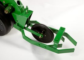
 Furrowers with solid or notched leading blade
Used in tilled soil to move dry soil away from the planting unit path to plant in moist soil.
NOTE: Cannot be used on row spacing of less than 30 in.
Furrowers are used in conservation tillage conditions to sweep trash and a small volume of soil to the sides to clear a path for the planting unit.
Furrowers have alternating right and left-hand leading blade to assure straight planter draft.
Effectiveness of furrowers is limited by the trash-cutting ability of the attachment.
Available with two 13-in. solid blades or with a notched blade in the leading position. Leading notched blade provides improved cutting action.
The blade mounting bracket is adjustable to change the contact angle for improved sweeping action.
Depth is easily adjustable. Convenient pointer and scale give easy-to-read reference point.
Furrowers are not compatible with unit or frame-mounted coulters.
Drive chain shields are required when using conservation disk furrower with planters that have drive/gauge wheels mounted to the rear. (Not required on 1760, 1770 12Row30 or 1780 Planters.)
Upforce / Downforce spring systems
Planter row-unit downforce is an important factor to ensure consistent and proper depth control. Downforce systems are used to keep the planting units from bouncing on rough seedbeds and to improve planter penetration in heavy residue and harder soil conditions. The amount of downforce required is determined by how the planter is equipped and the field conditions in which the planter is used.
Non-adjustable springs can also be used to apply upforce on the row-units. Upforce can be achieved by changing the orientation of the spring on the parallel arms. This upforce can be used to counteract excess
row-unit margin or extra weight cause by seed, tillage, or other attachments on the row-unit. Upforce springs will limit the maximum amount of downforce that can be place on a row-unit by the downforce system and should only be used in conditions were adequate and consistent depth control is easily maintained.
Non-adjustable springs in the upforce or downforce position can also be used to counteract variances in row to row. When used in conjunction with the pneumatic downforce system, non-adjustable springs can be used to provide a more consistent row-unit margin on each row by compensating for inconsistencies such as tire tracks, different row-unit tillage attachments, and other various attachments.
Non-adjustable springs
Non-adjustable springs, row-unit upforceA single set of springs apply approximately 90 lb of upforce / downforce per row. Two sets of springs can be used for 180 lb of force per row.
Non-adjustable downforce springs are recommended for use in conventional tilled soil for planting speeds over 5 mph and/or in rough-tilled seedbed conditions. Non-adjustable springs can be used with tillage attachments in lighter, conventional tilled soils. (Not recommended for use with unit- or frame-mounted coulter.)
Dual upforce springs 1700 TRAdjustable heavy-duty springs
Adjustable, heavy-duty downforce springsAdjustable, heavy-duty downforce can be used to apply 0 lb to 400 lb of downforce per row and has four settings: 0 lb, 125 lb, 250 lb, and 400 lb. The adjustable, heavy-duty downforce system can be used in all planting conditions and is compatible with all tillage attachments (recommended with unit-mounted coulter, row cleaners, and unit-mounted double-disk fertilizer openers in conservation planting conditions).
- NOTE: Compatible with all MaxEmerge™ Plus planters. Vacuum planters built prior to June 1992 require updated manifold brackets (A52970) to eliminate adjustment interference.
 17.8-cm x 17.8-cm (7-in. x 7-in.) single-disk opener installed
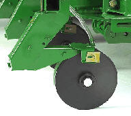 Double-disk opener assembly
Frame-mounted fertilizer openers are recommended for the following tillage conditions:
Openers | Conventional | Reduced | Moderate, no-till | Moderate, double crop |
Single disk | X | X | X | X |
Double disk | X | X |
|
|
Depending on the model, single-disk or double-disk frame-mounted fertilizer openers options are available to meet a wide range of operating conditions. The single-disk frame-mounted fertilizer opener is the most robust and versatile of the two frame-mounted options.
There are two designs of frame-mounted single disk fertilizer openers available for planters today:
- One design mounts to rigid frame or folding planters and utilizes a steel upper arm for secure mounting. This style opener is shown in the right-hand picture above and has been available for a number of years.
- The second design of frame-mounted single-disk openers is strictly for 17.8-cm x 17.8-cm (7-in. x 7-in.) frames and is for use on the 1775NT and 1795 Planters (excluding the 24Row20). This design incorporates a longer curved upper casting and is shown in the left-hand picture above.
Single-disk fertilizer openers feature a gauge wheel to:
- Gauge fertilizer application depth
- Minimize soil disruption
The frame-mounted, single-disk opener has the ability to be locked up in the raised position on 1795 Split-Row Planters. This eliminates excessive wear to the openers when planting soybeans with a 1795 and the openers are not utilized. There are two bundles required for updating 1795 Split-Row Planters. One bundle is used for the center frame section and the other bundle is for wing sections.
The frame-mounted, single-disk opener cannot be locked up in the raised position on 1775NT Planters due to frame tube and opener contact. The steel opener for rigid or folding planters (non-NT) can be raised somewhat by screwing up the spring assembly but cannot be completely raised from the soil.
NOTES:
- Single-disk openers on 8Row30 1755 frames are limited to placement of 7.6 cm to 15.2 cm (3 in. to 6 in.) off the row on rows 4 and 5.
- Single-disk opener is not recommended for loose, soft soil conditions unless equipped with cast spout.
- Single-disk opener has optional heavy-duty spring A50733 (Parts) if more down force is needed in tough no-till conditions.
- Double-disk opener is not compatible with frame-mounted coulter.
NOTE: Order number of opener bundles to match number of planter row units (i.e., 4Row 1755 Planter requires four BA91211 double-disk openers or two BA91212 single-disk openers).
 Unit-mounted liquid fertilizer injection opener
The single-disk, unit-mounted injection opener is available for many of the integral planter models along with some of the drawn planter models. It is capable of working in all soil conditions. However, it is best suited for no-till conditions in which the double-disk opener has limited residue cutting and penetration capabilities.
This system incorporates a 40.6-cm (16-in.) 50-flute blade for good cutting and penetration capabilities. The coulter blade runs 5.1 cm (2 in.) off the seed furrow.
This is an injection fertilizer opener system. The coulter blade opens the soil; a 1.3-cm (1/2-in.) tube and nozzle assembly injects the fertilizer into the trench. Application rates are 22.4 L/ha (2.4 gal./acre) to 351.7 L/ha (37.6 gal./acre).
This single-disk opener is not compatible with any other row tillage or row-unit-mounted attachment.
 Floating row cleanerFloating row cleaner side view
When paired with a unit-mounted coulter, the floating combo row cleaner offers the ultimate solution for managing tough residue and soil conditions. The row cleaner clears the way of debris, and the coulter penetrates tough soil, opening the furrow for the row unit opener blades. The floating ability of the row cleaner allows the unit to adapt to varying terrain independently of the row unit.
Features
The floating row cleaner allows a row cleaner to be used in conjunction with a unit-mounted coulter.This combination is often desired in heavy residue loads and tough reduced tillage planting conditions. The floating row cleaner features the SharkTooth® wheel. The beveled, sharpened edge of the teeth on the SharkTooth aggressively cuts flat and standing residue in the path of the row unit. The curved tooth design sweeps a clear path for the unit mounted coulter and opener blades, and resists residue buildup.
When used with the unit mounted coulter, the wheels are run side-by-side. They may be operated with one wheel forward if desired, by simply relocating the wheels to existing holes on the row cleaner bracket. The wheel bearings of the floating row cleaner are sealed and require no regular maintenance.
Cast aluminum depth gauge bands are standard equipment on the floating row cleaner. These durable bands are mounted directly to the row cleaner wheel, and aid the row cleaner in maintaining a consistent operating depth over varying terrain. The depth gauge bands also add weight to the row cleaner, aiding penetration in tough conditions. The depth gauge bands may be removed if desired.
Adjustability
The floating row cleaner is designed with maximum terrain following flexibility in mind. The pin adjustment has multiple settings available in 6.4-mm (1/4-in.) increments. The primary method of operating is to limit the maximum depth of operation, and allow the row cleaner to float up when necessary. This is accomplished by placing the adjustment pin below the floating bracket, limiting downward travel, but permitting upward travel.
It is also possible to set the row unit in a manner allowing full float. Simply place the pin in the lowest setting, allowing the depth gauge bands to determine the operating depth up and down. In some conditions, it may be desirable to pin the unit in a fixed position. This may be accomplished by simply pinning through the floating arm, fixing the row cleaner arm to the row unit and allowing the row unit to control operating depth.
Operational notes
NOTES:
- Not compatible with any row spacing less than 76.2 cm (30 in.), except the 1790 Split-Row Planter.
- Not compatible with Deere/Bauer or Deere/Orthman planters.
- Drive wheel chain shields are recommended for use with row cleaner attachments.
- Long parallel arms are required for use on:
- 1750
- 1760NT
- 1770NT when used in conjunction with frame mounted fertilizer openers
- 1790 front rank when used with frame mounted fertilizer openers
- 1790 rear rank
- For available long parallel arm attachments for field conversion, please click here.
- Use of long parallel arms is recommended, but not required, when using the floating row cleaner on 1770 Flex Planters in conjunction with frame-mounted fertilizer openers. Use of long parallel arms on these machines will maximize the distance between the fertilizer openers and the row cleaner, preventing interference and maximizing residue flow.
- Other row cleaner designs are available for use without a unit mounted coulter, or for use with unit-mounted double disk fertilizer openers.
- Use of row cleaners and unit-mounted coulters is not recommended when surface application pre-plant herbicide is used prior to planting. when using pre-plant incorporated herbicide, the row cleaner should be adjusted to minimize soil disturbance so as not to reduce the effectiveness of the incorporated herbicide.
SharkTooth is a trademark of Yetter Manufacturing, Inc.
 Tine tooth incorporator
Designed to offer full flexibility to follow ground contours and effectively mix soil and chemicals. Also levels soil and leaves it loose to further reduce the chance for crusting or erosion.
Tooth angle and penetration are easily adjusted for more or less aggressive action depending on the soil texture.
- NOTE: Not compatible with disk closing system or seed packer wheel attachment.
 Rear band spreader shown with windshield
Includes granular insecticide (with components for seed furrow placement and front or rear band spreader capability) plus herbicide with rear-mounted spreader.
Insecticide can be placed ahead of closing wheels (in-furrow or banded) or behind closing wheels (banded). Hopper, hopper divider, drive, and meters are included.
Windshield is available to decrease wind effect on distribution pattern (order separately).
 Rear-mount spreader
In order to add dry chemical (herbicide) capability to planters equipped with MaxEmerge™ row units, the installation of the dry chemical hopper, meter, drive chains, rear-mounted spreader, and related attachment hardware are needed.
As seen fully assembled in the picture to the left, the herbicide spreader is equipped with a series of baffles that distribute the dry granules on the ground in a band approximately 14 in. wide. Along with the spreader assembly, a windshield is available to decrease the effect wind has on distribution pattern (order BA25340 separately).
- NOTE: Not compatible with the seed packer wheel attachment or disk closing system.
 Seed furrow placement
 Band spreader placement
Includes hopper, meter and both seed furrow placement and front band spreader components.
Granular chemical meters have a meter wheel for applications of up to 8 oz. per 1000 ft of row. For higher application rates, order the fluted roller for the meter (A50863) from Parts.
When seed furrow placement is used, insecticide is placed in seed furrow with the seed ahead of closing
wheel.
When band spreader is used, insecticide is placed on ground in a band approximately 7-in. wide ahead or behind closing wheels.
Available with regular or closed-chemical hopper lids.
- NOTES:
- 1. Using rear-mount bracket (Code 9450/BA24528) allows using band spreader behind closing wheels.
- 2. Not compatible with seed packer wheel attachment or disk closing system.
- 3. Not compatible with 3.0 bushel seed hoppers.
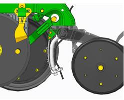 Hose guide is a flexible material and is black in production but shown in white in these images
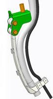 Hose guide
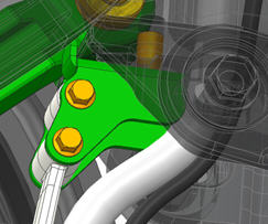 Hose guide
The in-furrow liquid fertilizer and dry insecticide row-unit attachment kit will be offered as an attachment for field conversion (AFC) only. It is compatible with MaxEmerge™ 5 row-units, ExactEmerge™ row-units, and older XP row-units with in-furrow fertilizer or with granular insecticide or with both. This attachment is designed to work with the 8-mm (0.3-in.) liquid in-furrow fertilizer hose and 1.9-cm (3/4-in.) dry insecticide hose. It can be configured in three different ways:
- To apply both liquid fertilizer and dry insecticide in the trench at the same time
- To apply liquid fertilizer only
- To apply dry insecticide only in the trench (not compatible with banding option)
This BA32912 kit is able to be installed to the closing system with the existing hardware using one bolt. This allows for a quick install and the tab on the front of the bracket keeps the orientation. No need to remove the gauge wheels or opener blades. The hose or hoses can be routed through the hole in the shank casting and closing wheel.
The BA32912 kit includes the following hardware and brackets
- A102159 x1 – guide
- A102158 x1 – bracket
- 14M7397 x2 – locknut
- 14M7746 x2 – locknut
- 19M8092 x2 – screw
- 19M9752 x2 – screw
- A103650 – electronic document
Other items needed based on number of kits order (most dealerships already have these supplies stocked):
- One zip-tie/tie strap per row (a 3.175-mm [1/8 in.] width is recommended)
- R96703 is recommend and has a quantity of one per package.
- 0.9 m (3 ft) of 8-mm (0.3-in.) hose per row
- A94657 is 200 m (656 ft) of hoses and would complete approximately 218 rows.
Rear-mount spreaderIn order to add dry chemical (herbicide) capability to planters equipped with MaxEmerge™ row units, the installation of the dry chemical hopper, meter, drive chains, rear-mounted spreader, and related attachment hardware are needed.
As seen fully assembled in the picture to the left, the herbicide spreader is equipped with a series of baffles that distribute the dry granules on the ground in a band approximately 14 in. wide. Along with the spreader assembly, a windshield is available to decrease the effect wind has on distribution pattern (order BA25340 separately).
- NOTE: Not compatible with the seed packer wheel attachment or disk closing system.
Seed furrow placementBand spreader placementIncludes hopper, meter and both seed furrow placement and front band spreader components.
Granular chemical meters have a meter wheel for applications of up to 8 oz. per 1000 ft of row. For higher application rates, order the fluted roller for the meter (A50863) from Parts.
When seed furrow placement is used, insecticide is placed in seed furrow with the seed ahead of closing
wheel.
When band spreader is used, insecticide is placed on ground in a band approximately 7-in. wide ahead or behind closing wheels.
Available with regular or closed-chemical hopper lids.
- NOTES:
- 1. Using rear-mount bracket (Code 9450/BA24528) allows using band spreader behind closing wheels.
- 2. Not compatible with seed packer wheel attachment or disk closing system.
- 3. Not compatible with 3.0 bushel seed hoppers.
 Liquid herbicide pre-emerge spray attachment
Applies pre-emerge liquid herbicide behind planting units.
Lower parts of attachment pivot rearward to prevent damage from obstructions such as corn stalks. Easy vertical adjustment permits quick setting of spray band width. Adapters are included to allow using flood tip nozzles for extended coverage. Approximate spray widths are:
- ''Even'' type spray tips are recommended for spraying in bands from 7 to 17 in. with the nozzle in the lower position (shown).
- The support tube may be inverted, placing the nozzle in the ''up'' position. Coverage in this position is from 50 to 90 in. in width when using flood type spray tips. This type of coverage is not recommended for less than 1/2 gallon per minute flow.
Check valves, nozzle bodies, and quick-attach nozzle caps are included for changing tips fast and easy without the use of tools. Also, this attachment for field conversion includes the distribution manifolds and hoses.
This attachment for field conversion does not include nozzle tips and strainers; see SprayMaster™ sprayer parts and accessories. Also, this attachment for field conversion does not include but requires (customer-supplied) tractor-mounted controls, tanks, pump and filters.
 Fertilizer pressure sensor for SeedStar17.8-cm x 17.8-cm (7-in. x 7-in.) single-disk opener installedDouble-disk opener assembly
Frame-mounted fertilizer openers are recommended for the following tillage conditions:
Openers | Conventional | Reduced | Moderate, no-till | Moderate, double crop |
Single disk | X | X | X | X |
Double disk | X | X |
|
|
Depending on the model, single-disk or double-disk frame-mounted fertilizer openers options are available to meet a wide range of operating conditions. The single-disk frame-mounted fertilizer opener is the most robust and versatile of the two frame-mounted options.
There are two designs of frame-mounted single disk fertilizer openers available for planters today:
- One design mounts to rigid frame or folding planters and utilizes a steel upper arm for secure mounting. This style opener is shown in the right-hand picture above and has been available for a number of years.
- The second design of frame-mounted single-disk openers is strictly for 17.8-cm x 17.8-cm (7-in. x 7-in.) frames and is for use on the 1775NT and 1795 Planters (excluding the 24Row20). This design incorporates a longer curved upper casting and is shown in the left-hand picture above.
Single-disk fertilizer openers feature a gauge wheel to:
- Gauge fertilizer application depth
- Minimize soil disruption
The frame-mounted, single-disk opener has the ability to be locked up in the raised position on 1795 Split-Row Planters. This eliminates excessive wear to the openers when planting soybeans with a 1795 and the openers are not utilized. There are two bundles required for updating 1795 Split-Row Planters. One bundle is used for the center frame section and the other bundle is for wing sections.
The frame-mounted, single-disk opener cannot be locked up in the raised position on 1775NT Planters due to frame tube and opener contact. The steel opener for rigid or folding planters (non-NT) can be raised somewhat by screwing up the spring assembly but cannot be completely raised from the soil.
NOTES:
- Single-disk openers on 8Row30 1755 frames are limited to placement of 7.6 cm to 15.2 cm (3 in. to 6 in.) off the row on rows 4 and 5.
- Single-disk opener is not recommended for loose, soft soil conditions unless equipped with cast spout.
- Single-disk opener has optional heavy-duty spring A50733 (Parts) if more down force is needed in tough no-till conditions.
- Double-disk opener is not compatible with frame-mounted coulter.
NOTE: Order number of opener bundles to match number of planter row units (i.e., 4Row 1755 Planter requires four BA91211 double-disk openers or two BA91212 single-disk openers).
17.8-cm x 17.8-cm (7-in. x 7-in.) single-disk opener installedDouble-disk opener assemblyFrame-mounted fertilizer openers are recommended for the following tillage conditions:
Openers | Conventional | Reduced | Moderate, no-till | Moderate, double crop |
Single disk | X | X | X | X |
Double disk | X | X |
|
|
Depending on the model, single-disk or double-disk frame-mounted fertilizer openers options are available to meet a wide range of operating conditions. The single-disk frame-mounted fertilizer opener is the most robust and versatile of the two frame-mounted options.
There are two designs of frame-mounted single disk fertilizer openers available for planters today:
- One design mounts to rigid frame or folding planters and utilizes a steel upper arm for secure mounting. This style opener is shown in the right-hand picture above and has been available for a number of years.
- The second design of frame-mounted single-disk openers is strictly for 17.8-cm x 17.8-cm (7-in. x 7-in.) frames and is for use on the 1775NT and 1795 Planters (excluding the 24Row20). This design incorporates a longer curved upper casting and is shown in the left-hand picture above.
Single-disk fertilizer openers feature a gauge wheel to:
- Gauge fertilizer application depth
- Minimize soil disruption
The frame-mounted, single-disk opener has the ability to be locked up in the raised position on 1795 Split-Row Planters. This eliminates excessive wear to the openers when planting soybeans with a 1795 and the openers are not utilized. There are two bundles required for updating 1795 Split-Row Planters. One bundle is used for the center frame section and the other bundle is for wing sections.
The frame-mounted, single-disk opener cannot be locked up in the raised position on 1775NT Planters due to frame tube and opener contact. The steel opener for rigid or folding planters (non-NT) can be raised somewhat by screwing up the spring assembly but cannot be completely raised from the soil.
NOTES:
- Single-disk openers on 8Row30 1755 frames are limited to placement of 7.6 cm to 15.2 cm (3 in. to 6 in.) off the row on rows 4 and 5.
- Single-disk opener is not recommended for loose, soft soil conditions unless equipped with cast spout.
- Single-disk opener has optional heavy-duty spring A50733 (Parts) if more down force is needed in tough no-till conditions.
- Double-disk opener is not compatible with frame-mounted coulter.
NOTE: Order number of opener bundles to match number of planter row units (i.e., 4Row 1755 Planter requires four BA91211 double-disk openers or two BA91212 single-disk openers).
To adapt 1730 and 1780 Rigid Planters liquid herbicide attachment for 15- through 20-in. row spacing applications. Contains manifold for up to eight rows and hose connector to pump.
Does not include manifold distribution parts for 1/4-in. hose and spray nozzles. Does not include any hose pump or control. Order hose through Parts.
Used to attach pre-emerge spray nozzles behind the planting units. Includes nozzle body but does not include the hoses or nozzle tips.
To adapt 1730 and 1780 Rigid Planters liquid herbicide attachment for 15- through 20-in. row spacing applications.
 PTO-driven hydraulic vacuum pump
A PTO-driven hydraulic pump allows operators to use the vacuum seed meter system with open-center hydraulic tractors and/or a 540 rpm or 1000 rpm PTO. The 540 rpm PTO system is compatible with 4Row through 9Row planters and provides 3.9 gpm at 80 percent of rated speed. The 1000 rpm PTO system is compatible with 4Row through 15Row planters and provides 5.0 gpm at 80 percent of rated speed. Both the 540 and 1000 rpm PTO pumps are for single vacuum motors only and inadequate for dual vacuum motors systems.
Flat seed disks such as edible bean and sweet corn require higher levels of vacuum. These disks require a dual vacuum motor configuration on planters over 8 rows. Neither the 540 or 1000 rpm PTO pump is adequate for flat seed disk operation.
9000 Codes include an oil cooler, except with 4-row planters with 540 rpm pump. When ordering PTO pump as a bundle, you must also order the oil cooler bundle, except with the 540 rpm PTO pump for 4-row applications.
Pneumatic downforce assemblyImproved pneumatic downforce systems are available as a factory-installed option on all planters and as a field conversion bundle for all MaxEmerge™ 5, MaxEmerge XP, MaxEmerge Plus, and MaxEmerge 2 planters. All pneumatic downforce field conversion bundles contain upgraded components to reflect pneumatic system upgrades for model year 2011.
Row-unit downforce is infinitely variable from 0 kg to 181.4 kg (0 lb to 400 lb). A gauge and/or display provides a reading as to how much downforce the system is providing. The downforce is constant at all times during operation.
On all model year 2011 and newer 1775NT, 1775NT Central Commodity System (CCS™), 1795, and DB Series Planters, the pneumatic downforce adjustment is displayed within the GreenStar™ 2 Display as base equipment. However, when converting a model year 2010 and older 1770NT, 1770NT CCS, 1790, and DB Series Planter, the air compressor assembly and gauge need to be mounted within the tractor cab, similar to factory-installed pneumatic downforce equipment configurations for that model year.
Each row-unit has a single air bag located between the parallel arms. The air bag is hooked in parallel so air can be added or released from all rows at once from one location. Split-row planters have the corn row-units and soybean rows plumbed separately, so the pressure can be removed from the bean rows when planting corn.
MaxEmerge 2 row-units with long parallel arms must have the arms changed to current production parallel arms. This ensures the correct hole pattern for pneumatic downforce. Refer to the attachment description to order the appropriate bundle for the frame size.
NOTE: Row-units with long parallel arms require A54544 spacer block if not so equipped (Service Parts).
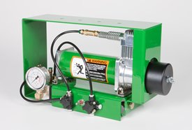 In-cab compressor assembly
An air compressor, located either in the tractor cab or on the frame, pumps up the system. Integral planter models ordered with pneumatic downforce from the factory have in-cab mounting as base equipment. For drawn planter models, the air compressor assembly is mounted onto the planter frame for model year 2011. Prior to model year 2011, the 1775NT, 1775NT CCS, 1795, and DB Series Planters have the air compressor mounted within the tractor cab from the factory.
Valves located on the compressor allow bleed-off of the system. Interplant rows are shut off entirely when those rows are locked up.
Field conversion bundles have been established for upgrading pneumatic downforce systems. With the bundle structure, order the individual components for a pneumatic downforce system. There are individual bundles for the air compressor, the row-unit downforce assembly, and a hose kit.
Each planter requires one air-compressor bundle, a number of row-unit downforce assemblies equal to the number of rows on the planter, and a hose kit for each 12 rows being equipped with pneumatic downforce. There are four different row-unit downforce assembly attachments. The selection of the row-unit downforce assemblies is based on the type of meter drive (chain or Pro-Shaft™ drive) and type of parallel arms being utilized (regular or long) on the row-units.
Pneumatic downforce assemblyImproved pneumatic downforce systems are available as a factory-installed option on all planters and as a field conversion bundle for all MaxEmerge™ 5, MaxEmerge XP, MaxEmerge Plus, and MaxEmerge 2 planters. All pneumatic downforce field conversion bundles contain upgraded components to reflect pneumatic system upgrades for model year 2011.
Row-unit downforce is infinitely variable from 0 kg to 181.4 kg (0 lb to 400 lb). A gauge and/or display provides a reading as to how much downforce the system is providing. The downforce is constant at all times during operation.
On all model year 2011 and newer 1775NT, 1775NT Central Commodity System (CCS™), 1795, and DB Series Planters, the pneumatic downforce adjustment is displayed within the GreenStar™ 2 Display as base equipment. However, when converting a model year 2010 and older 1770NT, 1770NT CCS, 1790, and DB Series Planter, the air compressor assembly and gauge need to be mounted within the tractor cab, similar to factory-installed pneumatic downforce equipment configurations for that model year.
Each row-unit has a single air bag located between the parallel arms. The air bag is hooked in parallel so air can be added or released from all rows at once from one location. Split-row planters have the corn row-units and soybean rows plumbed separately, so the pressure can be removed from the bean rows when planting corn.
MaxEmerge 2 row-units with long parallel arms must have the arms changed to current production parallel arms. This ensures the correct hole pattern for pneumatic downforce. Refer to the attachment description to order the appropriate bundle for the frame size.
NOTE: Row-units with long parallel arms require A54544 spacer block if not so equipped (Service Parts).
In-cab compressor assemblyAn air compressor, located either in the tractor cab or on the frame, pumps up the system. Integral planter models ordered with pneumatic downforce from the factory have in-cab mounting as base equipment. For drawn planter models, the air compressor assembly is mounted onto the planter frame for model year 2011. Prior to model year 2011, the 1775NT, 1775NT CCS, 1795, and DB Series Planters have the air compressor mounted within the tractor cab from the factory.
Valves located on the compressor allow bleed-off of the system. Interplant rows are shut off entirely when those rows are locked up.
Field conversion bundles have been established for upgrading pneumatic downforce systems. With the bundle structure, order the individual components for a pneumatic downforce system. There are individual bundles for the air compressor, the row-unit downforce assembly, and a hose kit.
Each planter requires one air-compressor bundle, a number of row-unit downforce assemblies equal to the number of rows on the planter, and a hose kit for each 12 rows being equipped with pneumatic downforce. There are four different row-unit downforce assembly attachments. The selection of the row-unit downforce assemblies is based on the type of meter drive (chain or Pro-Shaft™ drive) and type of parallel arms being utilized (regular or long) on the row-units.
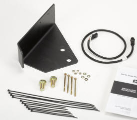 Mounting bracket and adapter harness
The planter radar is for SeedStarTM and ComputerTrakTM systems. The SeedStar and ComputerTrak 250, 350, and 450 monitor systems require radar.
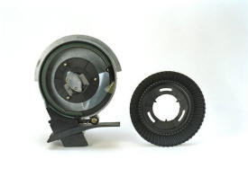 Radial bean meter
The radial bean meter is a mechanical meter to be used in conjunction with the finger pickup meter. Soybeans are the only crop compatible with the radial meter.
Those who are currently using the feed cup or competitive brush meters for soybeans and who desire improved spacing and population control should consider the radial meter.
A seed bowl mounts to the meter housing and rotates around the meter housing, singulating seeds for enhanced spacing.
The seed bowl clearance is adjusted in relationship to the meter housing as seed size is changed. Seeds, ranging from 2000 seeds per lb to 4500 seeds per lb, are planted with the one seed bowl.
Brushes mounted on the meter housing act as doubles eliminators and cleaners for the seed bowl.
Meter utilizes a sprocket-type wheel to better eliminate any beans being stuck in the seed bowl and to offer greater wear characteristics.
Meter component life is at least 650 acres per row, prior to wear appearing, for minimum maintenance.
NOTES:
- Radial bean meters require A58634 clip from Service Parts to install meters on 1997
- and earlier 3-bu fiberglass hoppers
- The radial bean meter is also available for MaxEmerge™ planters by ordering AA45061 from Parts.
Radial bean meterThe radial bean meter is a mechanical meter to be used in conjunction with the finger pickup meter. Soybeans are the only crop compatible with the radial meter.
Those who are currently using the feed cup or competitive brush meters for soybeans and who desire improved spacing and population control should consider the radial meter.
A seed bowl mounts to the meter housing and rotates around the meter housing, singulating seeds for enhanced spacing.
The seed bowl clearance is adjusted in relationship to the meter housing as seed size is changed. Seeds, ranging from 2000 seeds per lb to 4500 seeds per lb, are planted with the one seed bowl.
Brushes mounted on the meter housing act as doubles eliminators and cleaners for the seed bowl.
Meter utilizes a sprocket-type wheel to better eliminate any beans being stuck in the seed bowl and to offer greater wear characteristics.
Meter component life is at least 650 acres per row, prior to wear appearing, for minimum maintenance.
NOTES:
- Radial bean meters require A58634 clip from Service Parts to install meters on 1997
- and earlier 3-bu fiberglass hoppers
- The radial bean meter is also available for MaxEmerge™ planters by ordering AA45061 from Parts.
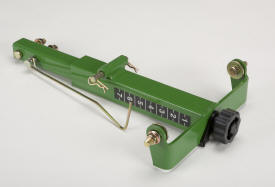 Row tillage support bracket
Includes pointer, scale, and large easy-to-use adjustment knob for convenient adjustment to desired working depth.
Required with tine tooth tillage, conservation furrower, and V-wing attachments when ordered as extra equipment.
NOTES:
1) Not compatible with unit- or frame-mounted coulters or heavy-duty parallel arms.
2) For MaxEmerge™ 2 planters built prior to June 1991, order A52092 cast lower parallel arm.
 Heavy-duty scrapers
Recommended for extremely sticky soils where even rotary scrapers have problems keeping Tru-VeeTM disks clean.
Scraper blades are heat treated for added wear.
- NOTE: Not compatible with any row-unit tillage attachments except conservation furrowers, unit-mounted coulter, and unit-mounted row cleaner.
Screw-adjust, unit-mounted row cleaner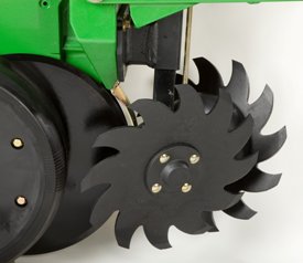 SharkTooth® wheel
The screw-adjust, unit-mounted row cleaner is mounted directly to the face plate of the row-unit, placing the ground-engaging components just in front of the row-unit opener blades and depth gauge wheels. This close proximity allows the gauge wheels to control the depth of the row cleaner as well as the row-unit. This compact design also allows greater compatibility with fertilizer openers and other planter attachments.
Features
The unit-mounted row cleaner features the SharkTooth® wheel. The beveled, sharpened edge of the teeth on the SharkTooth aggressively cut tough residue that lies in the path of the row-unit. The curved-tooth design sweeps a clear path for the openers and resists residue buildup. The wheels are arranged in a staggered fashion with one wheel leading the other, ensuring complete clearing of the row-unit path. The bearing on the SharkTooth wheel is sealed and requires no regular maintenance. Bearing shields are used between the wheel and the mount bracket to prevent residue wrapping and buildup around the bearing housing.
Adjustability
The unit-mounted row cleaner offers a convenient screw adjustment feature for changing the depth setting. The acme screw is enclosed within the structure of the mounting bracket, providing protection from the elements. The adjustment knob for the screw adjustment is accessible from the top of the parallel arms. The knob can be adjusted by hand or by using a socket. The adjustment is detented in 1.6-mm (1/16-in.) increments, allowing for quick, easily repeatable adjustments across all rows of the planter. An indicator rod and scale on the front of the row cleaner bracket indicate the current setting. If a condition is encountered where use of the row cleaner is not desired, it can be set so that the wheels do not engage the soil surface.
Operational notes and compatibility
Use of row cleaners is not recommended when surface application pre-plant herbicide is used prior to planting. When using pre-plant incorporated herbicide, the row cleaner should be adjusted to minimize soil disturbance so as not to reduce the effectiveness of the incorporated herbicide.
Drive chain shields are recommended for use with row cleaner attachments.
NOTES:
- Not compatible with use of frame-mounted coulter.
- Not compatible with any row spacing less than 76.2 cm (30 in.).
- For 1790 12/23, 12/24, 16/31, and 16/32 row machines, unit-mounted row cleaners recommended provided on the front rank of row units only.
- For DB60 47R15 machines, unit-mounted row cleaners are recommended on the 24 row units with short parallel arms only.
- Other row cleaner designs are available for compatibility with unit-mounted coulters and row unit-mounted double-disk fertilizer openers.
- Bundle is not compatible with long parallel arms. If purchasing for use on a long parallel arm machine, a separate bracket must be ordered from Service Parts.
- Drive wheel chain shields are not required on 1760, 1770 12Row30 (non-NT), or 1780 Front-Fold Planters.
- Drive wheel chain shields are required on other compatible models. Order BA25697 for the 1750 Standard Planter. Order BA24093 for all planters except the 1750 Standard.
SharkTooth is a trademark of Yetter Manufacturing, Inc.
 Plastic 3.0 bushel hopper and lid
Attachments for field conversion are available for complete seed hoppers and lids. Includes plateless and vacuum plastic 1.6 or 3.0 bushel seed hopper and lid. Seed meter, drive, and latch must be ordered separately if needed. These are for MaxEmerge™ XP rows only.
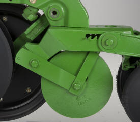 Seed packer wheel
For use when planting cotton in special growing conditions found primarily in southwestern United States.
Some particularly difficult soil types found in these areas are susceptible to severe ''baking and crusting'' if sufficient wind, soil moisture, temperature and sunlight conditions are present. In these situations, it is important to achieve adequate seed/soil contact while minimizing soil surface compaction.
Includes a wheel that runs ahead of the closing wheels to press the cotton seed into the bottom of the furrow.
Using the packer wheel enables the regular closing wheels to be used with a minimum force setting.
Wheels should not be used in the following conditions:
- Moist soil conditions.
- Contour planting application.
- Reduced tillage conditions (typical corn-belt conditions).
Not compatible with:
- Front band insecticide spreader.
- Rear-mounted herbicide/insecticide attachments.
- Disk closing.
 Unit-mounted coulter (shown with fluted blade)
Adapts planter to plant in reduced tillage conditions.
Nodular iron coulter arm mounts directly to planting unit shank to utilize full unit weight for penetration.
Unit gauge wheels provide depth control.
Coulter blade is positioned directly ahead of Tru-Vee™ opener to ensure accurate tillage in seed zone.
Rippled or fluted blades are available to suit a wide range of tillage and soil conditions.
NOTES:
1) Not compatible with tine tooth tillage, furrower attachments, V-wing bed sweep frame-mounted coulter or unit-mounted row cleaner.
2) Ballast attachment (or fertilizer attachment) may be required for penetration.
3) BA28970 or BA28971, heavy-duty adjustable downforce springs or pneumatic downforce system, are required to provide increased coulter penetration in hard soils and also to help keep unit from bouncing when being operated on rough seedbeds. (Not included with BA30078).
4) Requires A52092 cast heavy-duty lower regular parallel arm (one row) or A84382 heavy-duty lower long parallel arm (one row) from Service Parts. Heavy-duty long parallel arm is designed for use only with the unit-mounted coulter (not for tillage tool support bracket). Cast lower parallel arms have been standard equipment for a number of years, confirm what lower parallel arm subject planter is equipped with.
Fertilizer pressure sensor for SeedStarPTO-driven hydraulic vacuum pumpA PTO-driven hydraulic pump allows operators to use the vacuum seed meter system with open-center hydraulic tractors and/or a 540 rpm or 1000 rpm PTO. The 540 rpm PTO system is compatible with 4Row through 9Row planters and provides 3.9 gpm at 80 percent of rated speed. The 1000 rpm PTO system is compatible with 4Row through 15Row planters and provides 5.0 gpm at 80 percent of rated speed. Both the 540 and 1000 rpm PTO pumps are for single vacuum motors only and inadequate for dual vacuum motors systems.
Flat seed disks such as edible bean and sweet corn require higher levels of vacuum. These disks require a dual vacuum motor configuration on planters over 8 rows. Neither the 540 or 1000 rpm PTO pump is adequate for flat seed disk operation.
9000 Codes include an oil cooler, except with 4-row planters with 540 rpm pump. When ordering PTO pump as a bundle, you must also order the oil cooler bundle, except with the 540 rpm PTO pump for 4-row applications.
PTO-driven hydraulic vacuum pumpA PTO-driven hydraulic pump allows operators to use the vacuum seed meter system with open-center hydraulic tractors and/or a 540 rpm or 1000 rpm PTO. The 540 rpm PTO system is compatible with 4Row through 9Row planters and provides 3.9 gpm at 80 percent of rated speed. The 1000 rpm PTO system is compatible with 4Row through 15Row planters and provides 5.0 gpm at 80 percent of rated speed. Both the 540 and 1000 rpm PTO pumps are for single vacuum motors only and inadequate for dual vacuum motors systems.
Flat seed disks such as edible bean and sweet corn require higher levels of vacuum. These disks require a dual vacuum motor configuration on planters over 8 rows. Neither the 540 or 1000 rpm PTO pump is adequate for flat seed disk operation.
9000 Codes include an oil cooler, except with 4-row planters with 540 rpm pump. When ordering PTO pump as a bundle, you must also order the oil cooler bundle, except with the 540 rpm PTO pump for 4-row applications.
Monitor System
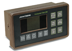 ComputerTrak 350
 The ComputerTrak 350 monitors use electronic circuitry, radar distance measuring, and a large liquid crystal display to provide sophisticated monitoring with simple operation. Along with this, the ComputerTrak 350 can monitor up to 32 rows simultaneously.
The ComputerTrak 350 monitor solution is available as an optional feature for the following planter and drill models:
| Drawn planters | Integral planters | Drills |
| 1750 Planter Series | 1700 Planter Series | 455 |
| 1760 Planter Series | 1710 Planter Series | 1590 |
| 1760NT Planter Series | 1720 8-Row and 12-Row Planters | |
| 1770 Planter Series | 1730 Planter Series | |
1780 Planter Series |
All other planter configurations will only have SeedStar™ 2 monitoring system available with no option for the ComputerTrak 350 monitoring system.
ComputerTrak 350 features include:
- Liquid crystal display provides operator with information regarding the planter function
- High/low warning alarm provides warning limits for seed population; this allows the operator to set the upper and lower population limits at which a warning is given
- Monitors population by row scan, by individual row, or by the minimum/average/maximum features; the minimum/average/maximum feature alternately displays row number and data for the lowest and highest population and the average population
- Displays seed spacing or population for all rows, showing the minimum/average/maximum for all rows
- Radar distance measuring is base equipment; this can be field calibrated by the operator for improved accuracy
- Ground speed of the planter can be displayed
- Non-volatile memory allows the console to be disconnected from the battery and still retain the program
- Built-in self-diagnostics check the continuity of all monitor sensor circuits upon power-up, providing up-and-ready display
- Console is easy to program for special planting patterns such as skip rows, etc.
- Monitor alarm can be turned off when multiple outside planting units indicate no seed flow, such as when using the half-width disconnect
- Enables accumulating count of seeds planted by a single row for any distance
- Allows measuring the total distance required to plant a desired quantity of seeds
- A second acre counter, allowing two counters of area to be used
- Split function allows two different planter configurations; this complements the 1790 for corn and soybean operations
- Population adjustment allows a fudge factor to be used to adjust the displayed population for situations when the calculated population is not being correctly displayed
NOTE: ComputerTrak 350 monitors require a radar input. Radar is ordered separately from monitor.
In the event of a radar or radar input failure, the ComputerTrak 350 monitor has the capability to continue with the monitoring of seed flow. If a disk-failed message occurs on this monitor, a set speed, or known as speed-set mode, can be entered to allow continued operation until the radar or radar input error has been resolved.
When in speed-set mode, fast average, area, and speed readouts will not be available. Row-failed messages will occur when seed count drop below two seeds per second. High- and low-population warning messages are also deactivated in this mode.
Also while in speed-set mode, the monitor is going to show fluctuating populations because it assumes the machine is traveling at a constant speed, even though actual populations may remain accurate at slower and faster speeds. Displayed population will only be close to actual populations when actual ground speed matches set speed.
To enter speed-set mode, please follow the following steps:
- Hold the split on/off switch while turning monitor on. A full display screen will be displayed for a few seconds and then the row-failed screen will display.
- Release the split on/off switch and press the setup-select switch. The speed screen will be the first displayed. The speed will be displayed in the lower right-hand corner of the display.
- Use the digit select and 0-9 switches to enter expected planting speed.
- Press the scan switch to being monitoring of seed flow.
If power is lost to monitor for any reason, hold the split on/off switch for one second while powering monitor on to re-enter speed-set mode. Previously entered speed is stored in memory and will not have to be re-entered.
NOTE: The speed-set mode is deactivated each time monitor is powered off.
Seed Hopper
Plastic 3.0 bushel hopper and lidAttachments for field conversion are available for complete seed hoppers and lids. Includes plateless and vacuum plastic 1.6 or 3.0 bushel seed hopper and lid. Seed meter, drive, and latch must be ordered separately if needed. These are for MaxEmerge™ XP rows only.