

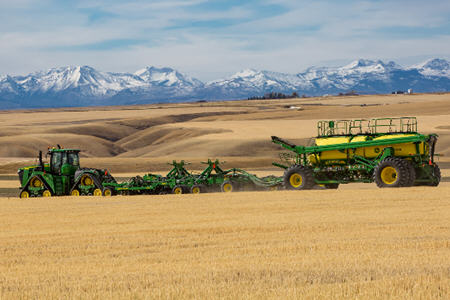
1895 no till air drill
Separate Fertilizer Placement (SFP) Air Drill
- New 60-foot model delivers 40% greater coverage
- Optional air seeder row markers
- Blockage warning systems can save skips in field
- Open center hydraulic check valve
View Product Brochure
Features
Growers have historically had to make some difficult planting and seeding decisions due to weather. Operators have been forced to plant in wet conditions that are far from optimal in order to plant within the optimum planting window. Those operators have experienced poor performance from wet soils working in between the depth gauge wheel and the opener disk and not having a way out. This creates the possibility of the depth gauge wheel or opener disk to seize up and drag through the soil.
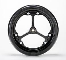
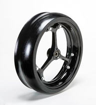
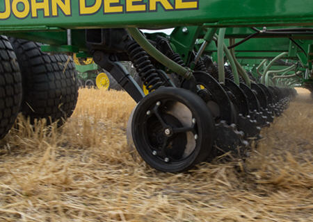
The spoke gauge wheel is a solution for operators who plant in these conditions to allow the mud and debris that get caught behind the depth gauge wheel to easily flow through the wheel and continue providing superior depth performance.
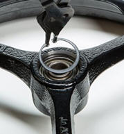
The spoke gauge wheel is designed for optimum performance. Its features include serviceable, stamped inner and outer rims. The wheel also has cast spokes and bearing hubs for increased strength. This allows smaller spokes, creating larger open surface area for mud and debris to flow more easily than competitor’s wheels. Another improvement over the closed gauge wheel is a snap-ring bearing retention. Simply remove the snap ring, replace the bearing, and place the snap ring back.
 Gauge wheel
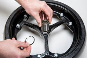 Gauge wheel
Heavy trash fields from no-till environments have also tested very well with the new spoke gauge wheel. Some growers provided feedback of crop residue getting inside and jamming up the gauge wheel and opener. This spoke gauge wheel has shown exceptional performance within these areas as well. These wheels are compatible with both 90 Series openers on seeding tools and planter row-units.
Below is a chart that demonstrates a competitive advantage over MudSmith™ wheels for mud and residue flow:
| MudSmith | John Deere | Percent improvement | |
| Open area | 329 cm2 (51 cu in.) | 471 cm2 (73 cu in.) | 43 percent |
| Rim height | 1.9 cm (3/4 in.) | 1.4 cm (9/16 in.) | 25 percent |
| Spoke width | 3.5 cm (1-3/8 in.) | 1.9 cm (3/4 in.) | 45 percent |
The wheel is serviceable along with other parts.
- AA86055 – complete wheel assembly
- A101570 – inner wheel rim half
- A101571 – outer wheel rim half
Not compatible in dual gauge wheel applications.
MudSmith is a trademark of MudSmith, LLC.
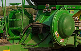 Air Power 2 fan system
Enhanced air seeding performance would not be possible without the updates to the 15,152.8-L (430-bu) and 19,381.5-L (550-bu) 1910 and C850 Air Carts. For the wider seeding width, more fan capacity has been added.
Air Power 2 provides two independently controlled fans – one for seed and one for fertilizer. Along with large, 76.2-mm (3-in.) primaries, more accurate delivery rates are possible across the full width of the seeding tool, from opener to opener. Plus, Air Power 2 allows growers to deliver high rates under field operating conditions – up to 40 percent more product delivery per primary compared to the single-fan system.
Dual fans are required for tow-between and tow-behind carts on the 23.2-m (76-ft) 1870 and 18.3-m (60-ft) 1895 models along with the eight primaries. Each fan will direct air to one set of primaries. Two selective control valves (SCVs) are required for the fans. The fan speed will be controlled through the SCV flow control.
Air Power 2 will also be compatible with the current 17.1-m (56-ft) and 23.2m (76-ft) 1870 Air Hoe Drills, as well as the 13.1-m (43-ft) and 18.3-m (60-ft) 1895 Disk Drills, plus the 15.2-m (50-ft) and 18.3-m (60-ft) 1890 models. An option is available for stainless-steel primaries to resist corrosion from high fertilizer rates.
 C850 Air Cart
There is a slide at the meter to choose bottom or top shoot for each meter. There is also a valve on the tank pressure system to choose top or bottom shoot. This same valve is used to adjust the amount of air to the tank to create the proper pressure differential.
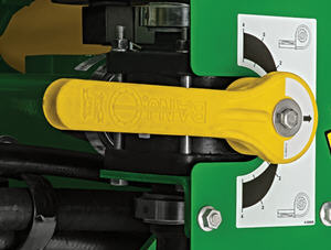 Tank pressure valve
The arrow on the valve handle should be pointing to the top of the range for the top shoot and the bottom of the range for the bottom shoot. If the tank will not be in use, set the pressure valve to the middle setting to not pressurize the tank. The operator should use the gauge to find the correct setting. An electronic pressure sensor will send a warning to the display if the tank pressure differential is out of range.
If pressure is in the green operating range, the tanks are sealed and operating correctly. The electronic pressure sensor is located behind the mechanical gauge on the side of the cart.
 RelativeFlow blockage sensing
With the RelativeFlow blockage system, operators can see the flow rate of both seed and fertilizer from inside the tractor cab. Sensors on delivery hoses monitor the relative rate of product flow. An easy-to-read display clearly visualizes relative product flow across the drill, from opener to opener. This exclusive technology gives a better view of what is happening across the tool in order to spot problems before blockage occurs.
RelativeFlow Blockage is available on the following models:
- 1890 - 15.2-m (50-ft) and 18.3-m (60-ft)
- 1870 - 12.2-m (40-ft), 17.1-m (56-ft), and 23.2-m (76-ft)
- 1895 - 18.3-m (60-ft)
- N500C – all widths
Below are the GreenStar™ 3 2630 Display screens for the blockage monitoring system. For complete details and information, see the owner’s manual.
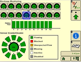 Blockage monitoring screen
The RelativeFlow system chart shows the amount of flow through each sensor on the selected tower. Sensitivity for the blockage system can be adjusted if desired, as shown below.
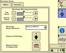 Blockage set-up screen
Blockage warning sensitivity allows the producer to set and change the sensitivity of the sensors to meet their preferences. Increasing the sensitivity means the system is more likely to show a false blockage, while less sensitivity means the system is more likely to miss a blockage.
Multiple run-page alarm behavior options are available for selection.
 Blockage set-up screen
Below are the Gen 4 display screens for the blockage monitoring system on the N500C.
For complete details and information reference, the owner’s manual.
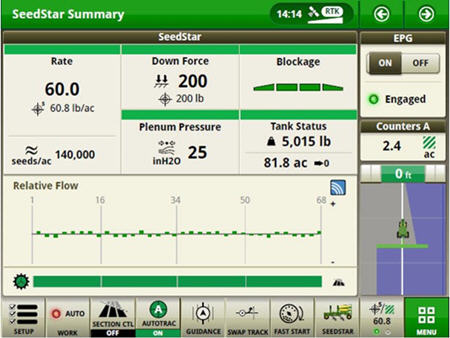 RelativeFlow Blockage configured run page
The SeedStar™ system run page displays the five major run settings. Clicking on any of the tiles will take an operator to that specific page (shown below).
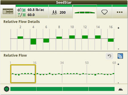 Operators can zoom into flow details by meter section when selecting Blockage tiles
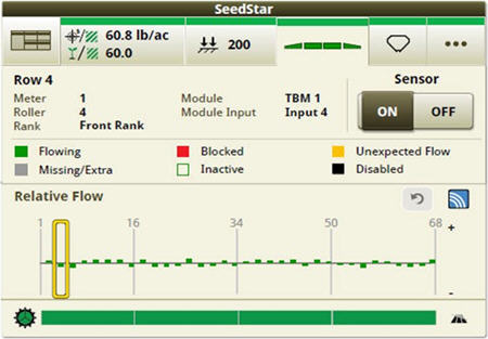 Operators can zoom into the row level to access row/sensor information and turn a sensor on/off independently
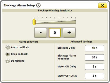 Blockage sensitivities and alarm delays are all set up on one easy-to-navigate screen
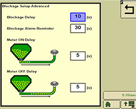
Blockage alarm delays can be set up by clicking on the advanced settings button from the blockage set-up screen.
- A blockage delay is how long a blockage should occur before an alarm is sounded.
- The blockage alarm reminder is how often the alarm should sound when a blockage occurs.
- The meter on delay is the time from when the meter is turned on until the blockage sensor should start monitoring for blockage.
- The meter off delay is the time from when the meter is turned off until the blockage sensor should start monitoring to verify no flow.
For more detailed information, see the owner’s manual.
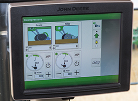 Downforce control from the cab
TruSet downforce control enables operators to conveniently set values for the seed and fertilizer ranks independently from the cab. This feature enables them to meet optimal downforce pressure while in varying soil conditions. TruSet downforce control improves seed placement accuracy in varying field conditions, leading to improved emergence and plant maturity.
TruSet system quick-reference guide
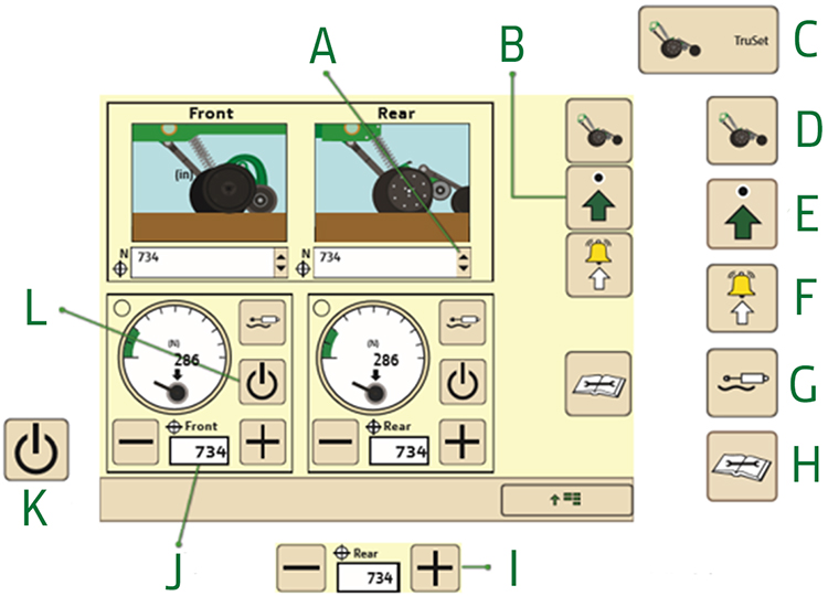
TruSet system quick-reference guide image key:
- Select here to choose from a list of programmed downforce setpoints.
- Select here to enter calibration screens, input downforce setpoints, and to verify the tractor selective control vavle (SCV) controlled by automation.
- TruSet – main menu button
- TruSet Run Screen
- Setup – select to configure tool
- Warning Setup – select to set downforce warnings
- Float Mode – select to toggle the float mode on and off. This option is only available using Power Beyond control options.
- Diagnostics – select to enter diagnostic information
- Press the plus or minus button to increase or decrease the downforce.
- Enter a value here to increase or decrease the downforce.
- Enables the downforce system
- Disables the downforce system
TruSet system tool setup
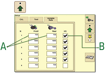 Tool setup
Select the tool setup to enter calibration screens, input downforce setpoints, and to verify the tractor SCV controlled by automation:
- Enter target setpoint for downforce
- Enable pick 6 prescription
TruSet system tool setup - automated SCV
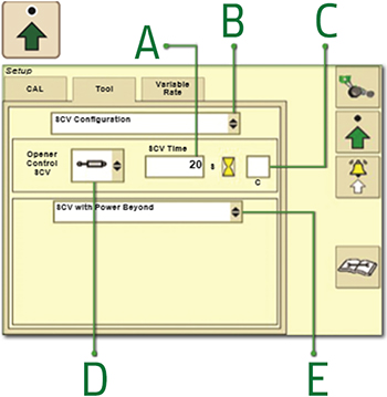
TruSet system tool setup - automated SCV image key:
- This is the time that the SCV remains on to ensure that Power Beyond activates.
- Select SCV configuration
- Enable or disable continuous SCV time
- Select opener control SCV (SCV1-6)
- Select opener control (SCV with Power Beyond, SCV only)
TruSet system tool setup - manual SCV
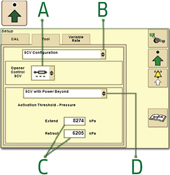
TruSet system tool setup - manual SCV image key:
- Select opener control SCV Manual (---)
- Select SCV configuration
- Enter values for the extend and retract thresholds if necessary
- Select opener control (SCV with Power Beyond, SCV only)
TruSet system tool setup - Implement Detection
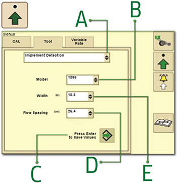
TruSet system tool setup - Implement Detection image key:
- Select Implement Detection
- Select tool mode
- Press to save the values
- Select row spacing
- Select nominal tool width
TruSet system tool setup - opener configuration
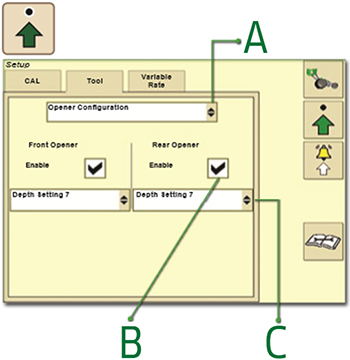
TruSet system tool setup - opener configuration image key:
- Select opener configuration
- Enable and disable opener control
- Select opener depth setting (1 through 13)
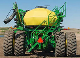
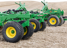 Tires on the 1895 Disk Drill
The 18.3-m (60-ft) 1895 Disk Drill offers larger mainframe and wing tires with higher floatation, resulting in less overall surface compaction while minimizing emergence issues. All tires on the 18.3-m (60-ft) machine are 207 kPA (30 psi). The mainframe and wing tires are equipped with casters and walking beams to allow for better ground following.
| Model | Width | Mainframe tire size | Wing tire size | Mainframe tire pressure | Wing tire pressure | Tire size | Flat-plate contact surface area |
| 1895 | 18.3 m (60 ft) | 550/45-22.5 | 33x15.5-16.5 | 207 kPa (30 psi) | 207 kPa (30 psi) | 550/45-22.5 | 1929 cm2 (299 in2) |
| 33X15.5-16.5 | 671 cm2 (104 in2) |
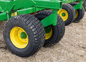 Wing tires
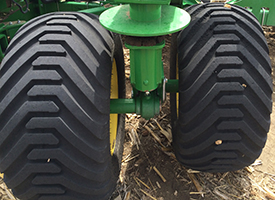 Mainframe tires
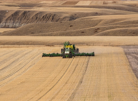 Wider width for more productivity
This 1895 Disk Drill is 18.3-m (60-ft) wide, which means 40 percent more working width over the current 13.1-m (43-ft) model. This gain in working width can save up to nine passes per quarter section during the same amount of time spent in the tractor cab.
An increase in productivity positively contributes to agronomics. Improving a grower’s productivity will increase the likelihood of hitting the seeding window while minimizing the chance for yield declines.
The opportunity for the 18.3-m (60-ft) 1895 model compared to the 13.1-m (43-ft) model is a $1,500 gain in wheat yield and $2,700 gain in canola yield from increased productivity. The productivity gain for the 18.3-m (60-ft) 1895 paired with a C850 Air Cart can save a grower up to nine passes per quarter section. Overall, this drill was designed for productivity and efficiency.
 SPF Openers
Separate fertilizer placement offers nutrient placement at a 5 or 7-degree angle
The 5-degree fertilizer opener:
- Is required for liquid and anhydrous (NH3) fertilizers
- Will also apply dry fertilizer
- Opens a smaller trench than the 7-degree opener
- Is better able to capture anhydrous and liquid fertilizer and seal fertilizers in the soil
Fertilizer tubes
There are four choices of interchangeable fertilizer tubes:
- Dry fertilizer tube to be used with 32-mm (1-1/4-in.) secondary fertilizer hose from the 1910 Cart
- Liquid fertilizer tube (for 13-mm [1/2-in.] i.d. hose)
- IMPORTANT: Using this tube for anhydrous may cause loss of retention
- Dual fertilizer delivery tube – allows for placement of dry or anhydrous. If applying both simultaneously, the operator may need to provide a relief system to relieve air from dry tube for adequate anhydrous retention. Without air relief, the operator will need to adjust air plenum to restrict all airflow to SFP dry tubes when anhydrous is being applied
- Anhydrous tube (for 10-mm [3/8-in.] i.d. hose)
- Liquid or NH3 fertilizer metering/delivery system is not provided by the John Deere Seeding Group
Key features of the SFP opener are:
- 457.2-mm (18-in.) opener blades operate at 5 degrees, resulting in a narrow trench with less soil disturbance
- Fertilizer tubes are interchangeable among dry, liquid, or anhydrous (NH3)
- Closing wheel assembly is closer to the fertilizer delivery tube; provides increased fertilizer retention
- Serrated closing wheels are base equipment on anhydrous openers and optional on liquid and dry openers
- NOTE: Closing wheels are recommended when dry soil conditions are common
- Extended-wear (chrome alloy) fertilizer boots are standard equipment
- Choice of five different gauge wheels
- Depth adjustments in 6-mm (1/4-in.) increments from 13 mm to 89 mm (1/2 in. to 3.5 in.) deep
Opener furrow-closing wheel
The 25-mm x 305-mm (1-in. x 12-in.) cast closing wheel follows the press wheel to close the furrow, placing soil over seed or fertilizer after the press wheel secures the seed in the furrow.
- A double-row ball bearing to reduce wear is located in the arm of the closing wheel
- Mounted parallel to the furrow opener, the closing wheel can be adjusted laterally to allow running on top of the furrow for sandy or mellow soils or to side of the furrow for heavier soils
- Down pressure is adjustable from 11.8 kg to 19.5 kg (26 lb to 43 lb) (no tools and three adjustments)
- A grease fitting in the pivot arm provides free movement for the arm
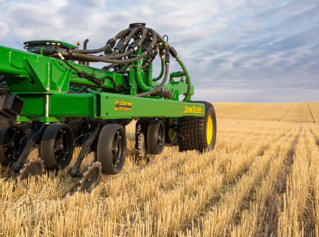 ProSeries Openers
ProSeries Openers are in base equipment on all 1890 and 1895 Separate Fertilizer Placement (SFP), 1990 Central Commodity System (CCS™), and 1590 Air Drills.
On the 1890 models, the single-disk openers are on 190-mm (7.5-in.) or 254-mm (10-in.) row spacing. On 15.25-m (50-ft) and 18.3-m (60-ft) 1890s, the 190-mm/380-mm (7.5-in./15-in.) or 254-mm/508-mm (10-in./20-in.) dual-row spacing feature is in base equipment. The single-disk openers provide consistent and accurate seed placement.
The ProSeries Openers are gang mounted and are hydraulically raised and lowered. The hydraulic downforce system also offers a wide range of downforce settings for the openers.
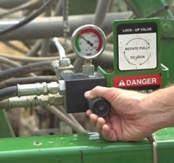 Active hydraulic downforce pressure valve
The active hydraulics:
- Work in conjunction with the opener spring
- Provide an adjustable range of 75 kg (165 lb) to 180 kg (400 lb) of down pressure per opener
- Benefit: penetrate hard soils and heavy residue
- The cylinders allow the openers to travel up or down an additional 405 mm (16 in.) with active hydraulic down pressure to follow the ground
- Provide the openers additional pressure when needed or allow the openers to go into relief if the pressure becomes too high
The down pressure:
- Is easily adjusted with the pressure valve located on the front of the mainframe
- Provides the operator the ability to quickly adjust, or dial in, the down pressure as operating conditions change
NOTE: For additional ballast in hard-to-penetrate conditions, tractor suitcase weights may also be added to the mainframe and wings to obtain maximum down pressure per opener.
The Proseries Openers:
- Work not only in no-till conditions, but also in minimum or reduced-till conditions
- Provide 51 mm (2 in.) of free travel in the opener before spring down pressure takes over
- Benefit: allows the opener to move over uneven ground conditions and minimize the chance of the gauge wheels bulldozing soil in soft or mellow conditions
- The opener spring travels a maximum of 200-mm (8-in.) up or 150-mm (6-in.) down before the hydraulics react to uneven seedbeds
Tractor, cart, and display compatibility
The 18.3-m (60-ft) tool is five sections with 254-mm (10-in.) spacing and is Air Power™ 2 compatible. This larger tool will require a 15,152.8-L (430-bu) tow-between cart, a 15,152.8-L or 19,381.5-L (430-bu or 550 bu) tow-behind cart, or the C850 Air Cart with Air Power 2 dual fan system. Along with this cart compatibility, breaks are required for this configuration due to the weight of the drill and cart vs. the tractor during transport mode. Below are compatible tractor, horsepower, display, and engine specific details.
Cart compatibility
- 1910 Carts equipped with Air Power 2
- 15,152.8-L (430 bu) tow-between cart
- 15,152.8-L (430 bu) tow-behind cart
- 19,381.5-L (550 bu) tow-behind cart
- C850 Air Cart
Along with the added tool size, the 1895 offers a heavy-duty hitch to pull an additional 20,412 kg (45,000 lb), which is the equivalent of two 7570-L (2,000-gal.) NH3 tanks when using a tow-between cart.
Tractor compatibility
- Recommended minimum 425-kW (570-hp) tractor with a 295.3-L/min (78-gpm) high-flow pump
- Follow recommended ballasting guidelines
- Requires a tractor with four selective control valves (SCVs) plus power beyond
- Requires a brake port for 1910 and C850 Air Cart brakes
- Flat ground - seeding less than (2.5 cm (1 in.)
- 425 kW (570 hp)
- Flat ground - seeding greater than 2.5 cm (1 in.)
- 462.3 kW (620 hp)
- Hilly terrain - seeding at any depth
- 462.3 kW (620 hp with tracks - recommended to obtain proper wheel slip)
- Flat ground - seeding less than (2.5 cm (1 in.)
Engine power capabilities

- The seeding tool system must be compatible with the maximum power that the largest Final Tier 4 (FT4) or comparable manufacturer’s tractor can produce.
- FT4 tractors have an advertised engine horsepower of up to rated power level of 462.3 kW (620 hp). Power bulge for short periods of time increase this to 499.6 kW (670 hp).
- Pulling a full 15,152.8-L (430-bu) cart requires about 51.5 kW (69 hp), the 19,381.5-L (550-bu) cart requires about 66.4 kW (89 hp), and the 29,953.2-L (850-bu) cart requires about 96.9 kW (130 hp).
Display compatibility

This larger tool was designed for the Gen 4 CommandCenter™ display. This technology integration saves time and money.
- 4600 CommandCenter™ display with Premium Activation
- 4640 Universal Display with core activation
Growers that may be interested in upgrading their current 90 Series Openers to the ProSeries Openers can do this by ordering a ProSeries retrofit kit.
Two kit offerings are available for seed openers, a two row (AA98693) and eight row (AA97392) kit. The breakdowns are as follows:
AA98693
| A105410 | Deflector, seed firmer tab | 2 pc |
| A107506 | Washer, special | 8 pc |
| A109343 | Seed boot, left hand | 1 pc |
| A109344 | Seed boot, right hand | 1 pc |
| A110307 | Closing arm spring, left hand | 1 pc |
| A110308 | Closing arm spring, right hand | 1 pc |
| A31869 | Locknut | 2 pc |
| AA88056 | Press wheel assembly | 2 pc |
| E55662 | Nut, 3/8 | 8 pc |
| N280653 | Washer | 2 pc |
| N283804 | Opener disk | 2 pc |
| N283976 | Nut, U-nut | 2 pc |
| N283308 | Screw, flange | 2 pc |
| 03H2070 | Bolt, round head | 8 pc |
| 19M7720 | Screw, hex | 2 pc |
| A105392 | Spiked seed closing wheel | 2 pc |
| A97699 | Instructions, dealer download | 1 pc |
AA97392
| A105410 | Deflector, seed firmer tab | 8 pc |
| A107506 | Washer, special | 32 pc |
| A109343 | Seed boot, left hand | 4 pc |
| A109344 | Seed boot, right hand | 4 pc |
| A110307 | Closing arm spring, left hand | 4 pc |
| A110308 | Closing arm spring, right hand | 4 pc |
| A31869 | Locknut | 8 pc |
| AA88056 | Press wheel assembly | 8 pc |
| E55662 | Nut, 3/8 | 32 pc |
| N280653 | Washer | 8 pc |
| N283804 | Opener disk | 8 pc |
| N283976 | Nut, U-nut | 8 pc |
| N283308 | Screw, flange | 8 pc |
| 03H2070 | Bolt, round head | 32 pc |
| 19M7720 | Screw, hex | 8 pc |
| A105392 | Spiked seed closing wheel | 8 pc |
| A117632 | Instructions, ProSeries | 1 pc |
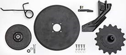 ProSeries seed opener kit
NOTE: Kits are subject to change.
Specifications
| Key Specs | 1895-no-till-air-drill Current Model |
|---|---|
| Working widths | 18.3 m 60 ft |
| Spacing | Seed spacing - 254 mm 10 in. Separate fertilizer - 508 mm 20 in. |
| Number of ranks | Two seed ranks and one separate fertilizer rank |
| Openers | Rank lock-up Front, middle, and rear Diameter 45.7 cm 18 in. Down pressure Hydraulic |
| Sizes | |
| Working widths | 18.3 m 60 ft |
| Spacing | Seed spacing - 254 mm 10 in. Separate fertilizer - 508 mm 20 in. |
| Number of ranks | Two seed ranks and one separate fertilizer rank |
| Number of sections | Three |
| Dimensions | |
| Transport height | 5.2 m 16.92 ft |
| Transport width | 5.7 m 18.83 ft |
| Road clearance | 21.59 cm 8.5 in. |
| Overall length | 11.6 m 38.17 ft |
| Centerframe width | 4.55 m 14.9 ft |
| Weight before ballast | 28,213 kg 62,200 lb |
| Available ballast | 1,451.5 kg 3,200 lb |
| Frame | Cross members 102 x 152 mm 4 x 6 in. End tubes 51 x 152 mm 2 x 6 in. Hitch 152 x 254 mm 6 x 10 in. |
| Clearance from rank to rank | 134.1 cm 52.8 in. |
| From ground to top of lid | |
| From ground to platform | |
| From ground to top of safety rail | |
| From ground to top of lights | |
| Centerline of mainframe wheel support tube to centerline of wing wheel support tubes | |
| Lateral frame clearance, opener to opener | |
| Tires | |
| Mainframe standard | (8) 42.1x 21.7x 22.5 in. 12PR |
| Mainframe bolt pattern | Duals with eight-bolt wheels |
| Wings standard | (16) 33x15.5-16.5 in. 10PR |
| Wings bolt pattern | Duals with eight-bolt wheels |
| Centerframe tires and wheels | |
| Wing tires and wheels | |
| Wheel spacing, center frame | |
| Openers | |
| Style | |
| Rank lock-up | Front, middle, and rear |
| Disk | Diameter 45.7 cm 18 in. Angle Seed at 7 degree (angle) Fertilizer (dry only) at 5 or 7 degree (angle) Single blade with beveled edge |
| Down pressure | Style Active hydraulic downforce 10-in. space 75 to 181 kg 165 to 400 lb Hydraulic |
| Depth control | Description Semi-pneumatic Gauge wheel size Standard - 11.43 x 40.64 cm 4.5 x 16 in. Narrow gauge wheel - 7.62 x 40.64 cm 3 x 16 in. Range 1.27 to 8.89 cm 0.5 to 3.5 in. Increments 0.64 cm 0.25 in. Gauge wheel |
| In-Furrow press wheel | Material Rubber-face press wheel Packing force 2.3 to 21 kg 5 to 45 lb 1.8 x 25.4 cm 0.71 x 10 in. |
| Furrow closing | Description Closing wheel - vertical 15 degree (angle) Size 2.54 x 30.48 cm 1 x 12 in. Material Cast iron Down force 12 to 20 kg 26 to 43 lb Yes |
| Double-Shoot capable | Yes - front ranks apply fertilizer |
| Seed Metering | |
| Description | |
| Crops | |
| Max Volumetric Seeding Rates - Barley | |
| Max Volumetric Seeding Rates - Oats | |
| Max Volumetric Seeding Rates - Rice | |
| Max Volumetric Seeding Rates - Milo/Sorghum | |
| Max Volumetric Seeding Rates - Soybean | |
| Max Volumetric Seeding Rates - Wheat | |
| Metering Drive Type | |
| Seed Storage | |
| Tank Description | |
| Total Tank Capacity | |
| Tank Fill Screen | |
| Tank Scales | |
| Seed Distribution | |
| Type | |
| Blower | |
| Blower drive type | |
| Distribution hose size | |
| Equipment compatibility (at 1.5 in. seeding depth and 8 mph) | |
| Tractor drawbar power required, 7.5-in (19.1 cm) models | |
| Tractor drawbar power required, 10-in (25.4 cm) models | |
| Tractor drawbar power required, 15-in (38.1 cm) models | |
| Tractor requirements | |
| Minimum number of SCV's | |
| Hydraulic Power Beyond | |
| Minimum hydraulic capacity | |
| Minimum electrical capacity |